Siemens VGD20.403U Instructions techniques - Page 5
Parcourez en ligne ou téléchargez le pdf Instructions techniques pour {nom_de_la_catégorie} Siemens VGD20.403U. Siemens VGD20.403U 14 pages. Gas valves, for use with skpxx.xxxu series electro-hydraulic actuators
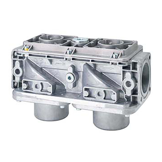
VGD Series Double Valves
Accessories
Part Number
AGF10.25U
AGF10.32U
AGF10.40U
AGF10.50U
AGA40.4050U
AGA40.6580U
AGA40.0100U
AGA40.0150U
AGA61
AGA66
Siemens AG Building Technologies Division
Single 1" connecting flange with ¼" port for VGD20.xxxU
Single 1¼" connecting flange with ¼" port for VGD20.xxxU
Single 1½" connecting flange with ¼" port for VGD20.xxxU
Single 2" connecting flange with ¼" port for VGD20.xxxU
1" NPT vent connection plate for VGD40.xxxU
1 ¼" NPT vent connection plate for VGD40.xxxU
2" NPT vent connection plate for VGD40.xxxU
2 ½" NPT vent connection plate for VGD40.xxxU
Manual adjusting throttle attachment AGA61 permits VGDxx.xxxU series valves to be used as
adjustable limiting orifice valves. Once adjusted, the AGA61 has a provision to be sealed from
tampering.
Sealing gasket to provide NEMA 3, NEMA 3R, and NEMA 4 protection.
Gasket kit to mount SKPxx.xxxU
‐ Place between actuator SKPxx.xxxU and valve VGDxx.xxxU
‐ Increases degree of protection from IP54 to IP65
‐ Refer to Mounting Instruction M7643.2 (74 319 0421 0)
Table 3. Accessories
Description
Document Number CC1N7631us
2 required per valve.
Order separately
Each vent connection
includes ¼" NPT test port,
see Mounting instruction
M7631.3 (74 319 0278 0)
Technical Instructions
November 08, 2017
Notes
Page 5