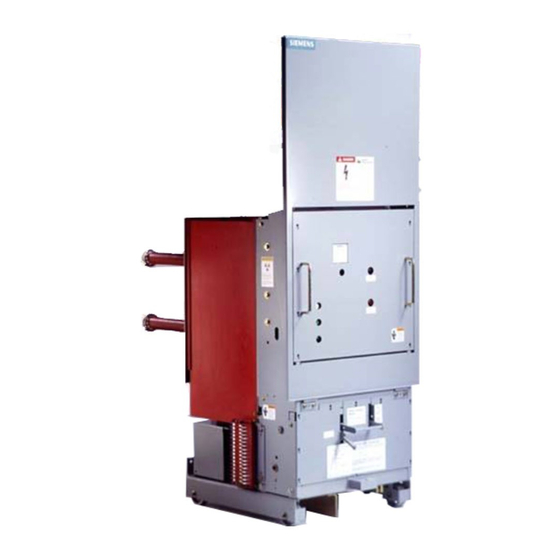
Siemens 15-FSV-750 Installation Fonctionnement et entretien - Page 25
Parcourez en ligne ou téléchargez le pdf Installation Fonctionnement et entretien pour {nom_de_la_catégorie} Siemens 15-FSV-750. Siemens 15-FSV-750 48 pages. Vacuum circuit breakers fsv series and msv series

Interrupter/Operator
Description
Secondary Release
Shunt releases (two trip coi ls) are used for the automatic or
manual tripping of the circuit breaker by su itable protective
relays or manual control devices when more than one is re
q u i red . They are generally intended for connection to a sepa
rate auxil iary supply (DC or AC)
Undervoltage Release
The u ndervoltage release is used for continuous monitoring of
the tri pping supply voltage . If this supply voltage fal ls exces
sively, the undervoltage release will provide for automatic trip
ping of the breaker .
The undervoltage device may be u sed for manual or relay trip
ping by employing a contact in series with undervoltage de
vice hold ing coil. Relay tripping may also be achieved by
employing a normally open contact in paral lel with the holding
coil. A resistor must be provided to l imit cu rrent when the nor
mally open contact is c losed.
Secondary and undervoltage releases are avai lable for all
standard ANSI Control Voltages.
Construction and Mode of Operation
The release consi sts of a spring-power storing mechanism, a
latching device and an electromagnet These elements are ac
commodated side by side in a housing, ( 1 6-3) with a detach
able cover and three through holes, ( 16-5), for fastening screws.
The supply leads for the trip coil are connected to a terminal
block, ( 16-33). Two lugs, ( 16-17 ) , are fitted beside the tripping
pin, ( 16-15), for the attac hment of a manual tripping lever.
The energy-storing mechanism consists of the striker p i n , ( 16-
23), and its operating spring, ( 16-31) , which is mostly located
inside the striker pin ( 16-23 ) . When the spring is compressed,
the striker pin is held by a latch, ( 16-25 ) , whose sloping face is
forced against the appropriately shaped striker p i n , (16-23) ,
b y spring , ( 16-27 ) . The other end o f t h e latch, (16-25), i s sup
ported by a partly mi lled locking pin , ( 16-21), (16a) pivoted in
the cover sheets of the magnet armature, ( 16-9). The armature,
(16-9), is pivoted in front of the poles of the U-shaped magnet
core, ( 16- 1 ), and is pul led away from it by the tension spring ,
(16-11)
If the magnet coil of the shunt release 3AX 1 1 0 1 is energized
by the tripping impulses or if the tripping p i n , ( 16-15), is me
chanically actuated, magnet armature, ( 16-9), is swung against
the pole faces. When this happens, the latch , ( 16-25), loses its
support and releases the striker pin, ( 16-23) , which is forced
out by the spring, ( 16-31)
On the undervoltage release 3AX1 1 03 the latc h , 25, is held by
the locking pin, ( 16-2 1 ) , as long as the armature, (16-9 ) , i s at
tracted , (Fig. 1 6b ) . If the ci rcuit of the trip coi l , (16-7), is i nter
rupted , the armatu re, ( 16-9), d rops off, thus causing the latch,
( 16-25) , to lose its s u p port and release the striker pin, ( 16-23).
Following every tripping operation the stri ker pin. ( 16-23). must
be reset to its normal position by load ing the spring. ( 16-31)
This takes place automatically via the operating mechanism of
the circuit b reaker.
S ince the striker pin of the undervoltage release 3AX 1 1 03 is
latched only when the armature is attracted . this trip is fitted
with a sc rew, ( 16-29) (see 1 6c), for locking the striker pin ( 16-
23), in the normal position for adjusting pu rposes or for carry
ing out trial operations during breaker servicing
1 3
1
Magnet core
3
Housing
5
Through-hold
for mounting screws
7
Magnet coil
9
Magnet armature
1 1
Extens1on spring
13
AdJUSting screw for 11
Figure 16 Construction of Shunt Release Shown
Released
23
25
2 1
Figure 16a. Latch Detail (16-25) Shunt Release Shown
Charged
Page 20
1 5
Tr1pp1ng pin
1 7
Lug for lever
2 1
Lock1ng p m
2 3
Str1ker pin
25
Latch
27
Spring
3 1
Stnker p1n spnng
33
Term1nal block
27
