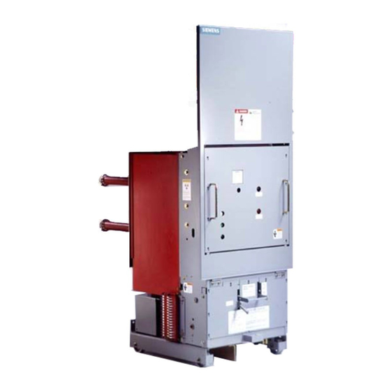
Siemens 15-FSV-750 Installation Fonctionnement et entretien - Page 44
Parcourez en ligne ou téléchargez le pdf Installation Fonctionnement et entretien pour {nom_de_la_catégorie} Siemens 15-FSV-750. Siemens 15-FSV-750 48 pages. Vacuum circuit breakers fsv series and msv series

Vehicle
Description
Insulating Barriers
Reference Figure 28
Insulating barriers are req u i red for use on type MSV and FSV
circuit b reakers.
I nterphase (with cutout) and exterior barriers on type FSV c i r
cuit breakers are removed or inserted by sliding them in the
vertical channels.
I nterphase barriers on type MSV circuit breakers are removed
or inserted by sliding them in the vertical channels. Exterior
barriers are secu red with the mou ntin g posts i nserted i nto the
teardrop holes and slid down to hold i n place. This may requ i re
a slight deflection of the barrier against the i nterrupter heat
sink.
Type MSV and FSV breakers req u i re a full compl iment of two
exterior and two i nterphase barriers. Refer to the parts guide
for location of barriers.
Figure 28 Insulating Barrier-Type FSV
Hinged Front Panel
Aramid Cords
G uides
Side View
Hinged Front Panel-Type FSV
Figure 29
Front Hinged Panel, Type FSV
FS V breaker
Reference Fig u re 29The
panel which is spring loaded to seek a vertical position Helical
extension springs maintain tension in aramid fiber cords which
are trained over g u ides to apply a horizontal pull on the front
panel towards the rear of the b reaker.
If the front panel fai ls to move easily and freely against the
spring tension. DO NOT FORCE. STOP ' Exam ine aramid cord
to ensure it is aligned over each of two guides. Tensioned cords
are applied symmetrically to each side of the front pane l . Hel
ical springs may be accessed by removing the front lower panel
of the breaker.
Page 39
-1
I
}
I
I
l
I
/
l/
Extension
Spring
employs a hi nged front
