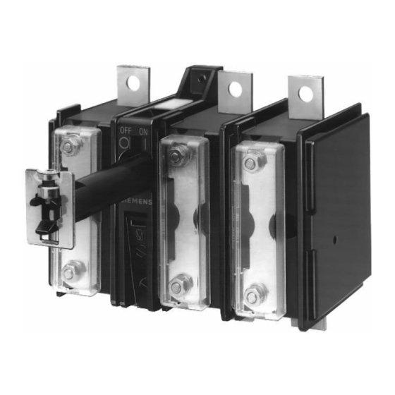
Siemens 3KA52 Brochure - Page 14
Parcourez en ligne ou téléchargez le pdf Brochure pour {nom_de_la_catégorie} Siemens 3KA52. Siemens 3KA52 50 pages. Switch-disconnector
Également pour Siemens 3KA52 : Mode d'emploi (5 pages)

SENTRIC Switch Disconnectors
SENTRIC K Switch Disconnectors from 63 A to 1000 A
Base mounting
■
Area of application
SENTRIC KA switch disconnectors are implemented as main
control switches and EMERGENCY-STOP switches for normal
switching duty and isolation of main circuits and auxiliary cir-
cuits. Another area of application is the switching of three-phase
induction motors and other loads for maintenance and repair
work.
■
Selection and ordering data
All switch disconnectors to the IP00 degree of protection
Conductor connecting screws are generally included in the scope of supply.
7
3KA53 30–1AE01
3KA53 30–1AE01
3KA53 40–1AE01
1) The nominal values are reduced in the case of strong harmonics due to fre-
quency converter operation.
7/14
Siemens LV 10 · 2004
Rated
DT
Complete
PS*
uninter-
version with
rupted
8UC6 door-cou-
current
pling rotary oper-
I
ating mechanism
u
(black handle)
A
Order No.
3-pole for motor loads
63
B
3KA50 30–1EE01 1 unit
80
B
3KA51 30–1EE01 1 unit
125
B
3KA52 30–1EE01 1 unit
160
B
3KA53 30–1EE01 1 unit
250
B
3KA55 30–1EE01 1 unit
400
B
3KA57 30–1EE01 1 unit
630
B
3KA58 30–1EE01 1 unit
3-pole for power distribution
63
B
3KA50 30–1EE01 1 unit
80
B
3KA51 30–1EE01 1 unit
125
B
3KA52 30–1EE01 1 unit
160
B
3KA53 30–1EE01 1 unit
250
B
3KA55 30–1EE01 1 unit
400
B
3KA57 30–1EE01 1 unit
630
B
3KA58 30–1EE01 1 unit
1
4-pole
) for power distribution
63
B
3KA50 40–1EE01 1 unit
80
B
3KA51 40–1EE01 1 unit
125
B
3KA52 40–1EE01 1 unit
160
B
3KA53 40–1EE01 1 unit
250
B
3KA55 40–1EE01 1 unit
400
B
3KA57 40–1EE01 1 unit
630
C
3KA58 40–1EE01 1 unit
Main control switches and EMERGENCY-STOP switches are
hand-operated switch disconnectors acc. to IEC 60947-3 and
VDE 0660 Part 107 (EN 60947-3) and comply with the isolation
conditions and the requirements of machine guideline
EN 60204-1.
Weight
DT Basic switch
PS*
per PU
version
ap-
without handle
prox.
Order No.
}
1.440
3KA50 30–1AE01
1 unit
}
1.400
3KA51 30–1AE01
1 unit
}
2.380
3KA52 30–1AE01
1 unit
}
2.420
3KA53 30–1AE01
1 unit
}
5.470
3KA55 30–1AE01
1 unit
}
5.550
3KA57 30–1AE01
1 unit
}
6.120
3KA58 30–1AE01
1 unit
}
1.440
3KA50 30–1AE01
1 unit
}
1.400
3KA51 30–1AE01
1 unit
}
2.380
3KA52 30–1AE01
1 unit
}
2.420
3KA53 30–1AE01
1 unit
}
5.470
1 unit
3KA55 30–1AE01
}
5.550
3KA57 30–1AE01
1 unit
}
6.120
3KA58 30–1AE01
1 unit
2.490 B
3KA50 40–1AE01
1 unit
2.540 B
3KA51 40–1AE01
1 unit
2.490 B
3KA52 40–1AE01
1 unit
2.450 B
3KA53 40–1AE01
1 unit
6.030 C
3KA55 40–1AE01
1 unit
5.150 B
3KA57 40–1AE01
1 unit
6.590 B
3KA58 40–1AE01
1 unit
* This quantity or a multiple thereof can be ordered.
Weight
DT
8UC6 EMER-
PS*
per PU
GENCY-STOP
ap-
door-coupling
prox.
rotary operating
mechanism (red
handle, yellow
indicator plate)
kg
Order No.
}
0.946
8UC61 21–3BB10
1 unit 0.353
}
0.918
8UC61 21–3BB10
1 unit 0.353
}
1.880
8UC62 22–3BB20
1 unit 0.426
}
2.020
8UC62 22–3BB20
1 unit 0.426
}
4.510
8UC63 23–3BB30
1 unit 0.999
}
4.630
8UC63 23–3BB30
1 unit 0.999
}
5.150
8UC63 23–3BB30
1 unit 0.999
}
0.946
8UC61 21–3BB10 1 unit
}
0.918
8UC61 21–3BB10 1 unit
}
1.880
8UC62 22–3BB20 1 unit
}
2.020
8UC62 22–3BB20 1 unit
}
4.510
8UC63 23–3BB30 1 unit
}
4.630
8UC63 23–3BB30 1 unit
}
5.150
8UC63 23–3BB30 1 unit
}
2.100
8UC62 22–3BB20 1 unit
}
2.110
8UC62 22–3BB20 1 unit
}
2.090
8UC62 22–3BB20 1 unit
}
2.240
8UC62 22–3BB20 1 unit
}
5.040
8UC63 23–3BB30 1 unit
}
5.190
8UC63 23–3BB30 1 unit
}
5.740
8UC63 23–3BB30 1 unit
Weight
per PU
ap-
prox.
kg
0.353
0.353
0.426
0.426
0.999
0.999
0.999
0.426
0.426
0.426
0.426
0.999
0.999
0.999
