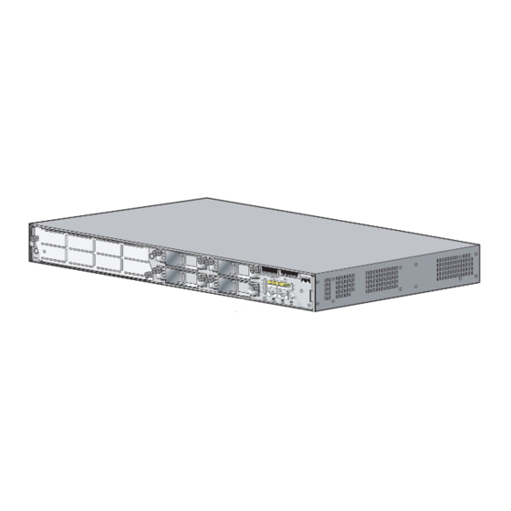
Cisco 2811 Series Installation et mise à niveau - Page 3
Parcourez en ligne ou téléchargez le pdf Installation et mise à niveau pour {nom_de_la_catégorie} Cisco 2811 Series. Cisco 2811 Series 14 pages. 2800 series integrated services routers
Également pour Cisco 2811 Series : Fiche technique (20 pages), Opérations (31 pages), Opérations (31 pages), Manuel de démarrage rapide (47 pages)

Make sure that the router is turned off and disconnected from its power source.
Step 1
Before opening the unit, disconnect the telephone-network cables to avoid contact with
Warning
telephone-network voltages. Statement 1041
If rack-mounting brackets are attached to the chassis, remove them, using a Phillips screwdriver.
Step 2
Remove the four screws at the back of the top cover, using a Phillips screwdriver.
Step 3
Perform the following steps to loosen the cover from the chassis:
Step 4
Insert the blade of the 1/4-inch screwdriver straight into the square hole on either side of the chassis
a.
near the back, so that it fits against the chassis and does not go past the chassis and into the narrow
slot. See
Make sure that the tip of the screwdriver does not slide into the narrow vertical slot that is visible inside
Caution
the square hole. The tip of the screwdriver should rest on the metal tab just inside the chassis cover and
to the right of the vertical slot.
Figure 1
With the screwdriver positioned as required in
b.
toward the back of the chassis to loosen one side of the cover. See
The friction fit may be fairly tight; however, if the cover does not move with moderate effort, make sure
Caution
that the screwdriver is not inserted into the narrow vertical slot.
Figure 2
Repeat
c.
78-17850-01
Figure
1.
Inserting the Screwdriver into the Side of the Chassis
Screwdriver must not
enter the vertical slot
Rotating the Screwdriver to Loosen the Chassis Cover
Step a.
and
Step b.
for the opposite side of the chassis.
Step a.
above, rotate the screwdriver a quarter turn
Installing and Upgrading Fans in Cisco 2811 Series Routers
Removing the Chassis Cover
Figure
2.
3
