ABB ACH580-01 BxR Frame R1 Manuel d'instructions - Page 7
Parcourez en ligne ou téléchargez le pdf Manuel d'instructions pour {nom_de_la_catégorie} ABB ACH580-01 BxR Frame R1. ABB ACH580-01 BxR Frame R1 8 pages.

REPLACEMENT INSTRUCTIONS | ACH580-01 BXR UL TYPE 1 & 12, R1/R2
Step
Instruction
14
Connect the input wires (from fuse block) to the Input Terminals of
the drive.
Yellow U1 to L1
Black V1 to L2
Red W1 to L3
R1 Frame: Using PZ2 bit, torque terminals to 5 in-lb (0.5 Nm).
R2 Frame: Using a PZ2 bit, torque terminals to 14 in-lb (1.5 Nm).
15
Connect the motor wires (from 1M contactor) to Motor Terminals of
the drive.
Yellow U2 to T1/U
Black V2 to T2/V
Red W2 to T3/W
R1 Frame: Using PZ2 bit, torque terminals to 5 in-lb (0.5 Nm).
R2 Frame: Using a PZ2 bit, torque terminals to 14 in-lb (1.5 Nm).
16
Re-install the CDPI
B
zip ties
.
Reconnect the RS485 terminal block
secure with two zip ties
Reconnect any control wiring removed in steps 3 and 4.
WARNING! This configuration does not support Safe Torque Off (STO)
functionality in bypass mode.
17
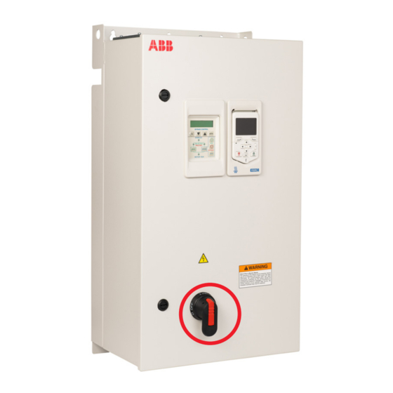
Close the door and rotate latches counterclockwise.
A
into control unit and secure with two
C
to EFB on control unit and
D
.
Diagram
A
B
7
C
D
