Actulux 111891 Manuel - Page 4
Parcourez en ligne ou téléchargez le pdf Manuel pour {nom_de_la_catégorie} Actulux 111891. Actulux 111891 20 pages.

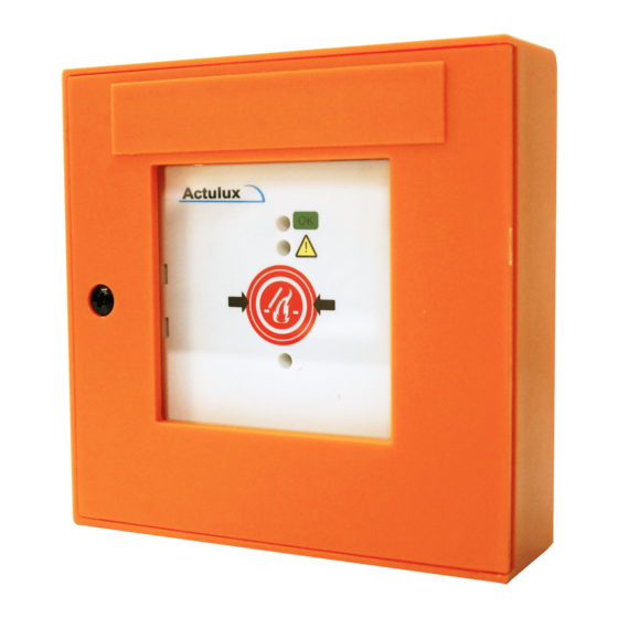
Fire Switch BVT for Smoke Ventilation Systems, IP40
EASY INSTALLATION AND OPERATION
The fire switch is developed to be used together with the
Actulux smoke ventilation system.
Connection diagram for BVT
Terminals:
1. green LED OK, lights when closing
2. Yellow LED, lights on error
3. red LED alarm, lights on emergency opening
4. ground (-)
5. -
6. fire switch emergency closing (reset)
7. fire switch emergency opening (fire)
Jumper J1 must only be set in the last or only fire switch
FEATURES
Function: Alarm (open), reset and off, sound indicator
LED indication: ''ok", "error" (yellow), "alarm activated'' (red)
Size: 125 mm x 125 mm x 36 mm (W x H x D)
Colour: Grey (can be delivered in orange on request)
Protection degree: IP40
Consumption on error: 2.2 mA
Item no.: 111789 (GREY) / 111790 (ORANGE)
4
for Actulux smoke ventilation systems
#111789
OPERATION INSTRUCTIONS
During fire: Break the glass and activate the red button.
During test open the lid and activate the red button.
Closing and alarm reset: Open the lid - activate the black
reset button, alarm is reset and skylights are closed.
24V
Grøn/Green
Grün/Vert
24V
Gul/Yellow
Gelb/Jaune
Buzzer
Buzzer
24V
Rød/Red
Rot/Rouge
Reset
2,2 KΩ
Alarm
10 KΩ
Jumper
J1
#111790
1
LED
OK
2
LED
3
LED
Alarm
4
GND
6
Reset
7
Actulux A/S
Haandvaerker
DK 9560 Had
Denmark
DRAWN BY: PSP
TITLE:
Diagram B
111693 Fir
