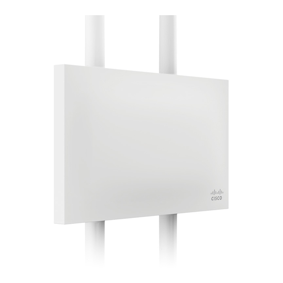
Cisco MERAKI MR72 Manuel d'installation du matériel - Page 4
Parcourez en ligne ou téléchargez le pdf Manuel d'installation du matériel pour {nom_de_la_catégorie} Cisco MERAKI MR72. Cisco MERAKI MR72 16 pages.
Également pour Cisco MERAKI MR72 : Manuel d'installation (20 pages)

2.2 Antennas and Ports
The Meraki MR72 has two radios. Each radio has two external antenna
connectors; both connectors for a particular radio should be attached
to the same type of antenna. The 5 GHz radio is used for mesh or client
communication. The 2.4 GHz radio is primarily used for client
communication. However, it can also communicate with Meraki 2.4
GHz access points.
Meraki offers a number of different antennas for use with the MR72:
MA-ANT-20, MA-ANT-21, MA-ANT-23, and MA-ANT-25.
The Meraki MA-ANT-20 omni-directional antennas must be installed
vertically.
The Meraki MA-ANT-25 patch antenna must be installed facing
downward, at least 30 degrees from the horizon line.
2.3 Power Source Options
The MR72 access point can be powered using either an 802.3at
capable PoE switch or the Meraki 802.3at PoE injector (sold
separately).
2.4 LED Indicators and Run Dark Mode
Your MR72 uses a single LED to inform the user of the device's status.
Function
LED Status
Meaning
