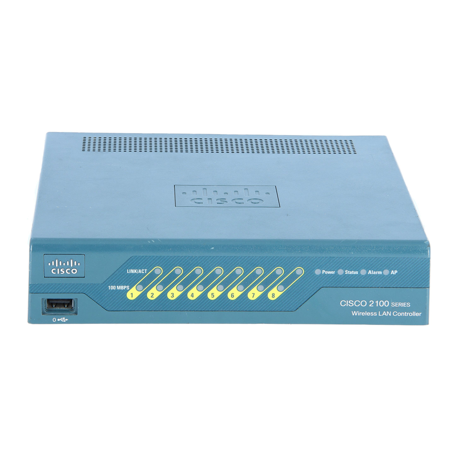
Cisco 5500 Series Manuel - Page 3
Parcourez en ligne ou téléchargez le pdf Manuel pour {nom_de_la_catégorie} Cisco 5500 Series. Cisco 5500 Series 19 pages. Cisco 8500 series
wireless lan controller
Également pour Cisco 5500 Series : Manuel de configuration (40 pages), Manuel d'installation (34 pages), Manuel de configuration (50 pages)

Chapter 7
Maintaining the Cisco Catalyst 5500 Multiswitch Router
Table 7-1
LED
SLOT 1
and
SLOT 0
100 Mbps
1000 Mbps Green
LINK
Ethernet Switching Module (10BaseT 24 Port) LEDs
Each switching module (Prod # WS-X5013) contains a STATUS LED. When on, this LED indicates that
the switching module is operational and is powered up. It does not necessarily mean that the interface
ports are functional or enabled.
The LEDs on the faceplate of the Ethernet switching module (10BaseT 24 Port) are described in
Table 7-2
Table 7-2
LED
STATUS
Link
Figure 7-2
ETHERNET SWITCHING MODULE
OL-0542-06
Supervisor Engine III and Uplink Module LED Descriptions (continued)
State
Description
On
Supervisor Engine III only: The Flash PC Card SLOT 1 and SLOT 0
LEDs light when their respective slot 1 and slot 0 Flash PC Card devices
are accessed.
Green
The port is operating at 100 Mbps.
The port is operating at 1000 Mbps.
Green
The port is operational.
Orange
The link has been disabled by software.
Flashing
The link is bad and has been disabled due to a hardware failure.
orange
Off
No signal is detected.
and shown in
Figure
7-2.
Ethernet Switching Module (10BaseT 24 Port) LED Descriptions
Description
The switch performs a series of self-tests and diagnostic tests.
If it passes all the tests, the status LED is green.
If it fails any test, the status LED is red (or orange for a minor fault or if manually
disabled).
If the port is operational (a signal is detected), the LED is green.
If the link has been disabled by software, the LED is orange.
If the link is bad and has been disabled due to a hardware failure, the LED flashes
orange.
If no signal is detected, the LED is off.
Ethernet Switching Module (10BaseT 24 Port) LEDs
3
6
9
12
15
18
21
24
2
5
8
11
14
17
20
23
1
4
7
10
13
16
19
22
Cisco MGC Software Release 7 Operations, Maintenance, and Troubleshooting Guide
Checking Equipment Status
7-3
