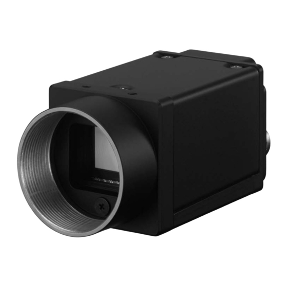
Sony XCG-CG240 Manuel - Page 8
Parcourez en ligne ou téléchargez le pdf Manuel pour {nom_de_la_catégorie} Sony XCG-CG240. Sony XCG-CG240 9 pages. Digital video camera
Également pour Sony XCG-CG240 : Manuel (9 pages)

White Balance (XCG-CG510C/CG240C/CG160C)
The white balance can be automatically adjusted when the
BalanceWhiteAuto command is executed. The detection area is
set to the screen center by default. The detection area can also be
displayed on the screen.
The detection frame can be changed arbitrarily (DetectAreaWBAuto).
For manual correction, the GainDigital should be changed.
GPIO
GPI
The signal level which is input in the 2nd, 3rd, and 4th* DC IN
connector can be detected. After selecting a connector by
LineSelector register, the signal level is acquired from LineStatus
register.
* Only output is available for XCG-CG160/CG160C/CG40
GPO
Various signals can be output from the 3rd and 4th DC IN
connector. After selecting a connector by LineSelector register
and setting LineMode to Output, LineSource is set. The output
polarity is set by LineInverter register.
Register
Parameter
Line 1 (0)
LineSelector
Line 2 (1)
Line 3 (2)
Input (0)
LineMode
Output (1)
Off (0)
LineInverter
On (1)
LineStatus
TriggerThrough (0)
ExposureActive (2)
StrobeActive (3)
SensorReadout (4)
UserOutput 1 (5)
LineSource
UserOutput 2 (6)
UserOutput 3 (7)
SignalTrue (8)
SignalFalse (9)
PWM (10)
Setting example:
The strobe control signal is output to GPO2 (DC IN connector 3rd pin)
by Hi active setting.
LineSelector = 1
LineMode = 1
LineInverter = 0
LineSource = 3
Memory shot
Memory shot is a function that controls the exposure timing and
image output to the network individually.
This is effective when multiple cameras are connected to the
same network and it is necessary to expose them at the same
time in a configuration that exceeds 1 Gbps band when operated
simultaneously.
Memory shot is available in multi-frame mode or single-frame
mode.
Number of images that can be saved is determined by image size
and pixel format.
Exposure start
Exposure
Imager readout
Camera output
XCG-CG510/CG510C/CG240/CG240C/CG160/CG160C/CG40
Setting
DC IN connector 2nd pin
DC IN connector 3rd pin
DC IN connector 4th pin
Set to output
Input setting
Without output inversion
With output inversion
Input signal level
Trigger through signal
Exposure signal
Strobe control signal
Sensor readout signal
User definition 1
User definition 2
User definition 3
Level H
Level L
Pulse generation signal
Sending of command
Reached the specified amount Event issued
Output timing control
Normally, images are sequentially output when exposure ends, but
the image output start timing can be delayed.
Optimal when requiring simultaneous exposure, but there are
several cameras connected to the same network and the
configuration makes the bandwidth exceed 1Gbps when operated
simultaneously.
Optimal when shooting 1 shot with single frame or trigger.
Exposure
Imager readout
Cam1
Camera output
Exposure
Imager readout
Cam2
Camera output
©2022 Sony Corporation
www.sony.co.jp/ISPJ/
ISPGC_E_22FEB
