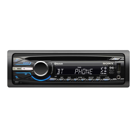
Sony MEX-BT3900U Manuel d'entretien - Page 34
Parcourez en ligne ou téléchargez le pdf Manuel d'entretien pour {nom_de_la_catégorie} Sony MEX-BT3900U. Sony MEX-BT3900U 48 pages. Bluetooth audio system
Également pour Sony MEX-BT3900U : Installation/Connexions (2 pages), Installation/Connexions (2 pages), Spécifications (4 pages), Installation/Connexions (2 pages), Dossier du propriétaire (45 pages)

MEX-BT39UW/BT3900U/BT3950U
Pin No.
Pin Name
59
DIAG
60
AMPSTB
61
CYRIL_SEL
62
VCC2
63
NCO
64
VSS
65
ILLUMI SEL
66
COLSW SEL
67
BT_MUTE
68
B-OUT SEL
AREASEL3 to
69 to 72
AREASEL0
73
R/S SW SEL
74, 75
NCO
76
INITCOL_SEL
77
BT_TX
78
BT_RX
79, 80
DEBUG_1, DEBUG_2
81, 82
RE-IN1, RE-IN0
83
NCO
84
BT_RTS
85
BT_CTS
86
BT_RESET
87
BT_POWER
88
BT_MIC_DET
89, 90
NCO
91
KEYACK0
92
KEYACK1
93
NCO
94, 95
KEYIN1, KEYIN0
96
AVSS
97
RC_IN0
98
AVRH
99
AVDD
100
LCD_CE
34
I/O
I
Diagnostic signal input from the power amplifi er
O
Standby control signal output to the power amplifi er
Cyrillic letter response setting terminal
I
Fixed at "L" in this set
―
Power supply terminal (+3.3V)
O
Not used
―
Ground terminal
I
Illumination voltage setting terminal
I
Setting terminal for the key illumination color
I
Muting on/off control signal input from the Bluetooth section
I
Blackout setting terminal
I
Destination setting terminal
I
REAR/SUB select setting signal input terminal
O
Not used
I
Key illumination initial color setting signal input terminal
O
Serial data output to the Bluetooth section
I
Serial data input from the Bluetooth section
O
Not used
I
Jog dial pulse input from the rotary encoder
O
Not used
O
RTS control signal output to the Bluetooth section
I
CTS control signal input from the Bluetooth section
O
Reset signal output to the Bluetooth section
O
Power on/off control signal output to the Bluetooth section
Microphone detection signal input terminal for the MIC IN jack
I
"L": MIC is disconnected, "H": MIC is connected
O
Not used
I
Acknowledge signal (wake up signal) input terminal for the rotary remote commander
I
Acknowledge signal (wake up signal) input terminal for the front panel key
O
Not used
I
Front panel key input terminal
―
Ground terminal (for A/D converter)
I
Rotary remote commander shift key input terminal
I
Reference voltage (+3.3V) input terminal (for A/D converter)
―
Power supply terminal (+3.3V) (for A/D converter)
O
Chip enable signal output to the LCD driver
Description
"H": corresponds to Cyrillic letter
"L": 9.0V, "H": 10.4V
"L": 2color, "H": 1color
"H": blackout effective (BT3950U only), Other models is "L"
"L": No switched
"L": reset
