Cisco ASA 5508-X Manuel d'installation du matériel - Page 7

Parcourez en ligne ou téléchargez le pdf Manuel d'installation du matériel pour {nom_de_la_catégorie} Cisco ASA 5508-X. Cisco ASA 5508-X 32 pages. Threat defense reimage guide
Également pour Cisco ASA 5508-X : Manuel de démarrage rapide (8 pages), Manuel d'installation facile (11 pages), Manuel de démarrage rapide (9 pages), Manuel du logiciel (37 pages), Monter et connecter (6 pages), Manuel (14 pages)
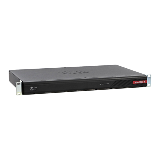
Cisco ASA 5508-X Manuel d'installation du matériel
Overview

Front Panel

The following figure shows the front panel of the ASA 5508-X. The ASA 5516 has an identical front panel.
There are 4 LEDS on the front panel. See
Figure 2: Front Panel

Rear Panel

The following figure shows the rear panel of the Cisco ASA 5508-X. The ASA 5516-X has an identical rear
panel.
Figure 3: Rear Panel
1
3
Online Only
Power switch
Standard rocker-type power
on/off switch.
Status LEDs
The locations and meanings of
the status LEDs are described
in
LEDs, on page
4.
LEDs, on page 4
for the descriptions.
2
Power cord socket
The chassis power-supply socket. See
Supply Modules, on page 7
about the ASA power supply.
4
Network data ports
Eight Gigabit Ethernet RJ-45 (8P8C) network I/O
interfaces. The ports are numbered (from left to
right) 1, 2, 3, 4, 5, 6, 7, 8. Each port includes a pair
of LEDs, one each for connection status and link
status. The ports are named and numbered Gigabit
Ethernet 1/1 through Gigabit Ethernet 1/8. See
Network Ports, on page 6
information.
Cisco ASA 5508-X and ASA 5516-X Hardware Installation Guide
Front Panel
Power
for more information
for additional
3