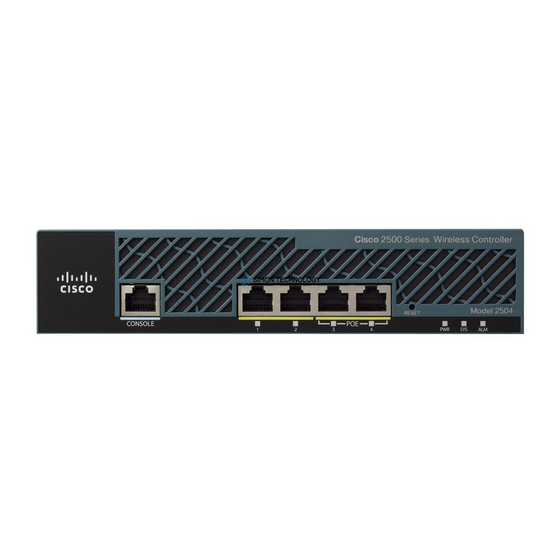
Cisco 2500 Series Manuel d'installation - Page 8
Parcourez en ligne ou téléchargez le pdf Manuel d'installation pour {nom_de_la_catégorie} Cisco 2500 Series. Cisco 2500 Series 12 pages. Wireless controller
Également pour Cisco 2500 Series : Manuel de configuration (19 pages), Manuel de déploiement (23 pages), Manuel de configuration (50 pages), Manuel de démarrage (47 pages)

Connecting the DC Power Supply
Connecting the DC Power Supply
This section describes the DC power supply specifications and wiring.
Warning
can only be gained by service personnel through the use of a special tool, lock and key, or other means of security,
and is controlled by the authority responsible for the location. (To see translated versions of the warning, refer to
the Regulatory Compliance and Safety Information document that accompanied your router.)
DC Power Specifications
The DC power supply is intended for use in DC operating environments. Table 1 lists the power supply
specifications.
Table 1
Description
Power (input)
Wire gauge for power connections 14 AWG
1. AWG = American Wire Gauge.
Wiring the DC Power Supply
Follow the directions in this section to wire the terminal block.
Warning
To ensure that all power is OFF, locate the circuit breaker on the panel board that services the DC circuit, switch
the circuit breaker to the OFF position, and tape the switch handle of the circuit breaker in the OFF position. (To
see translated versions of this warning, refer to the Regulatory Compliance and Safety Information document that
accompanied your router.)
Note
14 AWG copper conductors only. The installation must comply with all applicable codes.
Take the following steps to wire the terminal block:
Step 1
Step 2
Warning
appropriate lugs at the wiring end, as illustrated. The proper wiring sequence is ground to ground, positive to
positive (line to L), and negative to negative (neutral to N). Note that the ground wire should always be connected
first and disconnected last. (To see translated versions of this warning, refer to the Regulatory Compliance and
Safety Information document that accompanied your router.)
8 Installing Cisco AC and DC Power Supplies in Cisco 2500 Series Routers
This unit is intended for installation in restricted access areas. A restricted access area is where access
DC Power Supply Specifications
Design
Specification
40W, –40 to –72 VDC
Before performing any of the following procedures, ensure that power is removed from the DC circuit.
This product is intended for installation in restricted access areas and is approved for use with
Attach the appropriate lugs at the wire end of the power supply cord.
Wire the DC power supply to the terminal block, as shown in Figure 9.
The illustration shows the DC power supply terminal block. Wire the DC power supply using the
1
