Cisco IC3000 Documentation sur les produits - Page 5
Parcourez en ligne ou téléchargez le pdf Documentation sur les produits pour {nom_de_la_catégorie} Cisco IC3000. Cisco IC3000 12 pages. Industrial compute gateway
Également pour Cisco IC3000 : Manuel d'installation du matériel (37 pages)

Connecting DC Power
Warning:
When you connect or disconnect the power and/or alarm connector with power applied, an electrical arc
can occur. This could cause an explosion in hazardous area installations. Be sure that all power is removed from the
device and any other circuits. Be sure that power cannot be accidentally turned on or verify that the area is
nonhazardous before proceeding. Statement 1058
Warning:
Explosion Hazard—Substitution of components may impair suitability for Class I, Division 2/Zone 2.
Statement 1083
Warning:
In device installations in a hazardous location, the DC power source could be located away from the
vicinity of the device. Before performing any of the following procedures, locate the DC circuit to ensure that the
power is removed and cannot be turned on accidentally, or verify that the area is nonhazardous before proceeding.
Statement 1059
Warning:
Installation of the equipment must comply with local and national electrical codes. Statement 1074
Warning:
Before performing any of the following procedures, ensure that power is removed from the DC circuit.
Statement 1003
Warning:
Only trained and qualified personnel should be allowed to install, replace, or service this equipment.
Statement 1030
Warning:
A readily accessible two-poled disconnect device must be incorporated in the fixed wiring.
Statement 1022
To connect DC power:
Step 1
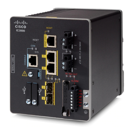
Locate the power connector on the IC3000 front panel.
Step 2
Identify the connector positive and return DC power connections. The connections are:
+ Positive DC power connection
- Return DC power connection
Step 3
Measure two strands of twisted-pair copper wire (18-to-20 AWG) (2.6mm) long enough to connect to the DC power
source.
Step 4
Using an 18-gauge (1.02mm) wire-stripping tool, strip each of the two
twisted pair wires coming from each DC-input power source to 0.25 inch
(6.3 mm) ± 0.02 inch (0.5 mm). Do not strip more than 0.27 inch (6.8 mm)
of insulation from the wire. Stripping more than the recommended amount
of wire can leave exposed wire from the power connector after installation.
Step 5
Remove the two captive screws that attach the power connector to the IC3000, and remove the connector.
5
