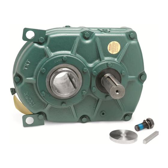
ABB Dodge SCXT605 Manuel d'instructions - Page 3
Parcourez en ligne ou téléchargez le pdf Manuel d'instructions pour {nom_de_la_catégorie} ABB Dodge SCXT605. ABB Dodge SCXT605 16 pages. Screw conveyor and hydroil screw conveyor drive

INSTALLATION
1.
Determine the running positions of the reducer (Figure 3).
Note that the reducer is supplied with 7 plugs; 5 around
the sides for horizontal installations and 1 on each face for
vertical installations. These plugs must be arranged relative
to the running positions as follows:
Horizontal Installations – Install the magnetic drain
plug in the hole closest to the bottom of the reducer.
Throw away the tape that covers the filter/ventilation plug
in shipment and install plug in topmost hole. Of the 3
remaining plugs on the sides of the reducer, the lowest one
is the minimum oil level plug.
Vertical Installations – Install the filter/ventilation plug in
the hole provided in the top face of the reducer housing.
Use the hole in the bottom face for the magnetic drain plug.
Of the 5 remaining holes on the sides of the reducer, use
a plug in the upper housing half for the minimum oil level
plug.
WARNING: To ensure that drive is not unexpectedly
started, turn off and lock out or tag power source before
proceeding. Failure to observe these precautions could
result in bodily injury.
HORIZONTAL APPLICATIONS
B
P
P
L
D
D
A-POSITION
B-POSITION
VERTICAL MOUNT
B
L
P
D
E-POSITION
B=BREATHER
D=DRAIN
Figure 3 - Mounting Positions
NOTE: If motor mount, motor and sheaves are to be
installed on reducer before mounting screw conveyor drive
to trough end, bypass step 2; perform steps 3 and 4, and
then return to step 2.
1.
Use lifting tab to hoist screw conveyor drive into position.
Slide shaft into screw and adapter over trough end studs.
Only one set of adapter holes will fit over the trough end
studs. If the mounted position of the screw conveyor varies
more than 15º from any of the four horizontal mounting
positions (Figure 1), an incorrect set of holes has been
selected for coupling adapter to reducer. This can be
corrected by removing adapter screws and rotating reducer
to its proper position. Reinstall and tighten adapter screws
to torque specified in Table 4. Install lockwashers and
tighten nuts on trough end studs. Attach drive shaft to
screw
2.
Remove the three bolts from reducer housing required for
mounting the SCD Motor Mount. Place the motor mount in
position and install the three housing bolts supplied with the
motor mount. Tighten bolts to torque specified in Table 4.
B
B
P
P
L
L
D
C-POSITION
D-POSITION
B
L
P
D
F-POSITION
L=LEVEL
3.
Install motor, drive sheave and driven sheave so that driven
sheave is as close to the reducer housing as practical.
Install V-belt and tension with the four adjusting screws
provided on the SCD Motor Mount. Install belt guard. Make
required electrical connections for motor.
WARNING: The user is responsible for comforming with
the National Electrical Code and all other applicable
local codes. Wiring practices, grounding, disconnects
and overcurrent protection are of particular importance.
Failure to observe these precautions could result in severe
bodily injury or loss of life.
4.
Because reducer is shipped without oil, it is necessary to
add the proper amount before operating the drive. Use a
high grade petroleum base, rust and oxidation inhibited (R
& O) gear oil –see lubrication tables.
B
L
D
5.
Retighten bolts and pipe plugs after a few days of peration.
This prevents oil leakage.
CAUTION: Unit is shipped without oil. Add proper amount
of
recommended lubricant before operating. Failure to
P=PLUG
observe these precautions could result in damage to, or
destruction of, the equipment.
Under average industrial operating conditions, the lubricant
should be changed every 2500 hours of operation or every six
months, whichever occurs first. Drain reducer and flush with
kerosene, clean magnetic drain plug, and refill to proper level
with new lubricant.
CAUTION: Too much oil will cause overheating and too
little will result in gear failure. Check oil level regularly.
CAUTION: Extreme pressure (EP) lubricants are not
recommended for average operating conditions. Failure to
observe these precautions could result in damage to, or
destruction of, the equipment.
Under extreme operating conditions, such as rapid rise and
fall of temperatures, dust, dirt, chemical particles, chemical
fumes, or oil sump temperatures above 200ºF, the oil should be
changed every 1 to 3 months, depending on the severity of the
conditions.
3
Figure 4 - Complete Drive
LUBRICATION
