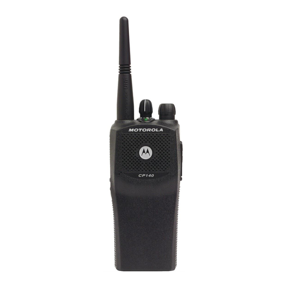
Motorola MDH65SDF9AA3AN Informations sur les services - Page 20
Parcourez en ligne ou téléchargez le pdf Informations sur les services pour {nom_de_la_catégorie} Motorola MDH65SDF9AA3AN. Motorola MDH65SDF9AA3AN 46 pages.

3-4
3.0
Troubleshooting Table for Transmitter
Symptom
No Transmit (no
1. PTT switch defective.
TX LED indication)
2. EXT MIC PTT fault
No Transmit (TX
1. Synthesizer out of lock Refer to
LED indication OK)
2. No TX_ENABLE
3. TX DC switch fault
4. Power control fault
5. No TX injection
6. No 5T source
7. TX gain stage failure
8. Antenna switch failure
Low Power
1. Low TX injection
2. Low gain in TX stage
3. Incorrect control volt-
age
4. Antenna switch defect
5. Harmonic filter defect
Possible Causes
Procedure
Verify U401-71 goes low when PTT
is pressed.
Verify U401-72 goes low when J471-
4 is grounded.
Synthesiser trouble-
shooting table
.
Verify U401-50 is high when pin 71
or 72 is low.
Verify Q171-C is 0V in TX.
Verify Q170-C is at Vbatt in TX.
Check Q150 and U150 dc voltages
Synthesiser
per schematic and
troubleshooting table
.
Check that RF level at jct. R100/
R101 per schematic.
Verify Q312 gate is 0V dc in TX
Verify Q312 drain is 5V dc in TX.
Check RF levels at Q100 and U110
per schematic.
Verify dc voltage at jct. R122/L120 is
approx 1.5V.
Check that RF level at jct. R100/
R101 per schematic.
Verify dc voltage at Q100-E is ~0.5V
(UHF).
Verify that RF level at U110-1 is
approx. 1.6V (UHF).
Verify that the dc voltage at
PWR_SET (R162) is approx 1.8V dc
(at 1 watt) to 2.6V dc (at 4-5 watts).
Verify that the dc voltage at U110-2
is approx 2-3V dc (at 1 watt) to 3-4V
dc (at 4-5 watts). (See schematic.)
Verify dc voltage at jct.R121/L120
(UHF) is approx 1.7V. Note: Do not
attempt to measure RF or DC
voltages at the diodes. Damage to
test equipment may occur.
Visually inspect components C130-
137, L130-132. Check dc continuity
of L130-132 in RX mode only.
TROUBLESHOOTING TABLES
Corrective Action
Replace PTT switch S441.
Check/replace Q470, L471 etc.
Synthesiser trouble-
Refer to
shooting table
.
Check/replace U401.
Replace Q171.
Check for shorts, replace Q170.
Repair/replace defective com-
ponents
Check U251, L291-292, C290-
291.
Check/replace Q313.
Check for shorts, check/replace
Q312.
Troubleshoot Q100/U110 and
associated circuitry.
Check/replace D120-121, L120-
121, R120-122, etc.
Check U251, L291-292, C290-
291.
Verify 5T voltage is correct.
Troubleshoot Q100 circuitry.
Troubleshoot Q100 circuitry.
Check/replace Q100.
Check programming. Trouble-
shoot controller circuitry. Check/
replace U451.
Troubleshoot U150, Q150 and
associated circuitry.
Check/replace D120-121, L120-
121, R120-122, etc.
Repair/replace if necessary.
