AEMC instruments CA7027 Manuel de l'utilisateur - Page 16
Parcourez en ligne ou téléchargez le pdf Manuel de l'utilisateur pour {nom_de_la_catégorie} AEMC instruments CA7027. AEMC instruments CA7027 20 pages. Fault mapper pro graphical tdr
Également pour AEMC instruments CA7027 : Manuel de l'utilisateur (20 pages)
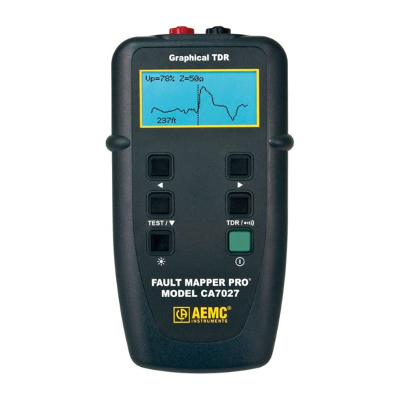
To determine the distance to an event, position the cursor at the beginning
of the event and read off the distance as shown below.
On the fault curve shown in the previous two screens, a low impedance
event occurs at 210 ft, shown by a downward spike on the curve, and a
high impedance event occurs at 413 ft.
The open end of the cable is shown as a large positive spike This is used
to determine the end (length) of the cable.
4.12 Single Shot and Continuous Scanning Modes
When the Fault Mapper Pro
Shot" mode.
In this mode, the Fault Mapper Pro
under test when either the
pressed.
To enter "Continuous Scanning" mode press and hold down the
TEST /
The
Continuous Scanning mode is active.
14
Find Quality Products Online at:
Vp=72% Z=100Ω
413ft
Single Shot Mode: Saves on battery life and also enables
the Fault Mapper Pro
while still leaving the fault display on the screen.
button.
icon will appear at the bottom right of the display, when
GlobalTestSupply
www.
is first switched on, it is set to "Single
®
only fires a pulse into the cable
®
and
buttons or the
®
to be disconnected from the cable
Fault Mapper Pro
TEST /
button is
®
Model CA7027
.com