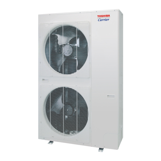
Toshiba Carrier MCY-MAP0607HS-UL Manuel d'installation - Page 15
Parcourez en ligne ou téléchargez le pdf Manuel d'installation pour {nom_de_la_catégorie} Toshiba Carrier MCY-MAP0607HS-UL. Toshiba Carrier MCY-MAP0607HS-UL 30 pages. Outdoor unit

6
Electric Wiring
WARNING
The equipment shall be installed in compliance with NEC and local codes.
Capacity shortages of the power circuit or an incomplete installation may cause an electric shock or fire.
CAUTION
• All field wiring insulation rating must comply with NEC and local codes.
• Do not connect 208/230 V power to the terminal blocks for control cables (U1, U2, U3, U4); otherwise, the unit may
break down.
• Be sure that electric wiring does not come into contact with high-temperature parts of piping; otherwise, the cable
coating may melt and cause an accident.
• After connecting wires to the terminal block, take off the traps and fix the wires with cord clamps.
• Do not conduct power to indoor units until vacuuming of the refrigerant pipes has finished.
• For the wiring of power to indoor units and that between the indoor and outdoor units, follow the instructions in the
installation manual of each indoor unit.
• Prepare an exclusive power supply for the air conditioner.
NOTE
• Use copper supply wires.
• Use UL wires rated 600 V for the system interconnection wires.
• Use UL wires rated 300 V for remote control wires.
Power supply specifications
Standard model
Model
Nominal Voltage, Phase and frequency
MCY-MAP0367HS-UL
MCY-MAP0487HS-UL
MCY-MAP0607HS-UL
Circuit breaker
EN-27
MCA: Maximum Circuit Amps
MOCP: Maximum Overcurrent Protection (Amps)
Power Supply
MCA
(A)
36.3
208/230 V -1- 60 Hz
36.3
36.3
Disconnect per NEC
and local codes.
Communication Wiring Specifications
Communication Wiring Design
Communication Wiring Summary
Outdoor unit
U1 U2 U3 U4
Central control
U1 U2
U3 U4
U1 U2 A B
Indoor unit
A
Remote control
MOCP
(A)
Communication wiring and central control wiring use 2-core non-polarity wires.
60
Use a 2-core shield wires to prevent noise trouble.
60
In this case, for the system grounding, close (connect) the end of shield wires, and isolate the end of terminal.
60
Use a 2-core non-polarity wire for remote control. (A, B terminals)
Use a 2-core non-polarity wire for wiring of group control. (A, B terminals)
– 14 –
Communication wiring between indoor and outdoor units
(Shield wire)
Communication wiring between indoor units (Shield wire)
U1
U2
A
B
U1
U
2
Indoor unit
Indoor unit
B
A
B
Remote control
Remote control
(Group control)
Installation Manual
A
B
U1
U
2
A B
Indoor unit
A
B
EN-28
