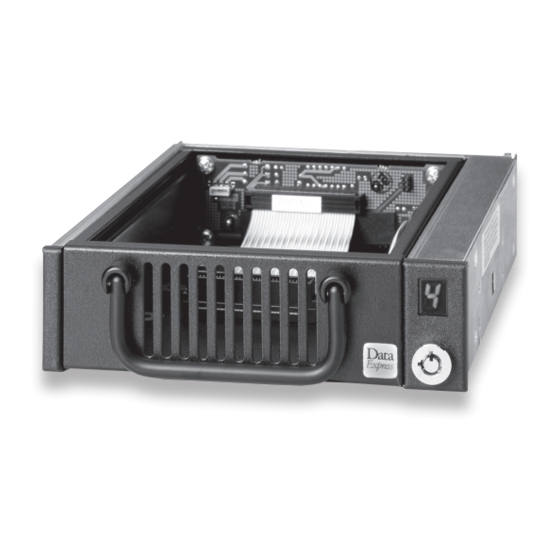
CRU DE100 Ultra 160 Manuel d'installation
Parcourez en ligne ou téléchargez le pdf Manuel d'installation pour {nom_de_la_catégorie} CRU DE100 Ultra 160. CRU DE100 Ultra 160 2 pages. 68-pin

DE100 Ultra 160 68-pin Install Guide
Removable SCSI Wide Ultra160 Drive Enclosure
Figure 1: Drive Installation Assembly
Receiving Frame Motherboard
Factory-Installed Jumpers (J4): There are two (2) jumpers factory-in-
stalled on J4. One jumper is located on Pins 7 & 8, the other on Pins 9 & 10.
NOTE: Do not remove jumpers! (Remove only if attaching the 6103-
1020-0000 Isolator Board.)
Option Pin Connector (W1)
Remote Unit ID Selection: Pins 1-8 are provided for remote unit ID selec-
tion for the computer system or expansion chassis. Remote ID selection
requires that the unit ID select switch located inside the receiving frame be
set to "0".
Remote Activity LED: Pins 9 & 10 provide power for a remote LED device
activity indicator.
Enable Termination Power Connector (W2): A jumper is installed at the
factory and enables termination power to/from the SCSI bus.
NOTE: Do not remove this jumper!
Rugged, Reliable, Mobile, Secure
Figure 2: Drive Installation Assembly
Note: The DE100 Ultra 160 may be shipped with an isolator/repeater
board factory-installed. If this is the case, your DE100 Ultra 160 will
look slightly different from figure above. Please refer to figure below
for receiving frame with isolator/repeater board attached (rear view).
The DE100 Ultra 160 Isolator/Repeater Board is an upgrade attach-
ment for the DE100 Ultra 160 receiving frame. This attachment pro-
vides both an enhanced, bus-isolating hot swap and repeater function.
1-800-260-9800
www.CRU-DataPort.com
TM
