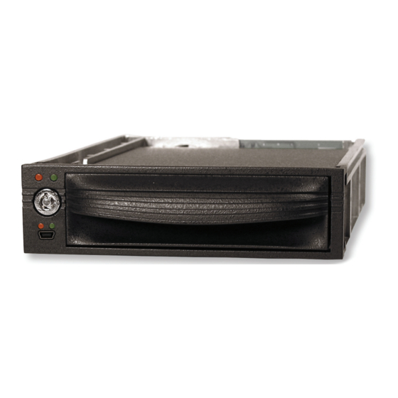
CRU DataPort 10 Secure AES 128 Manuel de l'utilisateur - Page 3
Parcourez en ligne ou téléchargez le pdf Manuel de l'utilisateur pour {nom_de_la_catégorie} CRU DataPort 10 Secure AES 128. CRU DataPort 10 Secure AES 128 7 pages.

Security Key
Encryption
Error LED
Power LED
Enabled LED
1.3 Warnings and Notices
Please read the following before beginning installation.
• The main circuit board of the HDD carrier is susceptible to
static electricity. Proper grounding is strongly recommended to
prevent electrical damage to the enclosure or other connected
devices, including the computer host. Avoid all dramatic
movement, vibration and percussion.
• Avoid placing the HDD carrier close to magnetic devices, high
voltage devices, or near a heat source, including any place
where the product will be subject to direct sunlight. Do NOT
allow water to make contact with any Security Keys, carrier or
receiving frame.
• Though the Security Key port is mechanically identical to the
standard Mini-USB port, inserting Security Keys into any other
Mini-USB port will damage the keys and render them useless.
Please only use Security Keys in DataPort Secure products.
• Likewise, inserting a Mini-USB cable or other device into the
DataPort 10 Secure Security Key port on the carrier can cause
internal damage and potentially lead to loss of data.
• Any time power is cycled on the DataPort 10 Secure, the
encryption key will need to be installed in order to access the
data on the drive.
2. Installation Steps
2.1 Receiving Frame Installation
a. Slide the receiving frame into an open 5.25" bay.
b. S ecure the receiving frame to the chassis with the four screws
provided.
c. A ttach the SATA data cable to the rear of the receiving frame
and the other end to the corresponding SATA port on the com-
puter's motherboard.
d. A ttach the SATA power connectors to the rear of the receiving
frame. If no SATA power connectors are available, attach the
included Molex-to-SATA adapter cable to a Molex power plug.
Then plug the SATA end of the adapter cable into the rear of the
receiving frame.
2.2 Hard Drive Installation
a. I f the carrier is bundled with a frame, use the included set of Data-
Port Keys to unlock the carrier and then remove it from the frame.
b. U se a Phillips-head screwdriver to remove the screw securing the
carrier cover to the back of the carrier, then slide the cover off.
c. I nsert a SATA hard drive into the unified power and data con-
nector inside the carrier.
d. S ecure the hard drive to the carrier by using the mounting
screws provided.
e. A ttach the Temperature Control Cooling Sensor to the top of the
hard drive with a piece of tape.
f. R eplace the cover and secure it with the screw you removed in
Step B. into the rear of the carrier.
g. Reinsert the carrier into the frame.
2.3 Operating your DataPort 10 Secure
a. I f you have not already done so, slide the DataPort 10 Secure
carrier into an open DataPort 10 frame (may be sold separately)
on your computer.
b. I nsert the Security Key into the Mini-USB Security Key Port on
the face of the receiving frame.
c. I nsert a DataPort Key into the key lock and turn it 90 degrees
clockwise to power on the unit.
d. W hen both green LEDs are lit, showing that the drive is ready
and encryption is activated, remove the Security Key and store
it in a safe location.
When any hard drive is first used with the DataPort 10 Secure it
will show up as a blank, unallocated drive and you'll need to format
the drive inside the enclosure before you can use it. Note that
formatting a drive will erase all data on the drive, so be sure
to back up your data before beginning this operation. See
Section 3 for instructions on how to format the drive with Mac or
Windows operating systems.
2.4 Safe Carrier Removal
a. T urn off the computer or properly dismount the drive from
Page 2
