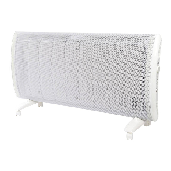
Dimplex WW 151 E Manuel d'installation et d'utilisation - Page 6
Parcourez en ligne ou téléchargez le pdf Manuel d'installation et d'utilisation pour {nom_de_la_catégorie} Dimplex WW 151 E. Dimplex WW 151 E 20 pages. Radiant panel heater
Également pour Dimplex WW 151 E : Manuel d'installation et d'utilisation (17 pages), Manuel d'installation et d'utilisation (20 pages)

English
Only use the device for room heating within en-
closed rooms.
Repairs on the heating device may only be carried
out by a qualified electrician or the after-sales ser-
vice.
Disconnect the power supply or switch off the
fuse in the event of fault or when the device is not
used for an extended period of time.
Do not operate the heating device in rooms where
highly flammable substances are used (e.g. sol-
vents, etc.).
Do not use the heating device if there are visible
signs of damage.
Do not use the heating device if it has tipped over.
2. Minimum clearances, notes on installation
The heating device may only be installed as shown, i.e.
on a horizontal, even surface. Using it on deep-pile
carpets is not permitted. Please use caution when in-
stalling it in front of flammable objects.
Minimum clearances must be observed.
In addition, a minimum clearance of 500 mm between
inflammable objects e.g. curtains, towels or heat-sen-
sitive plastics and the front of the unit must be main-
tained.
2.1 Use in the bathroom
The device must be used in such a manner that the
controls cannot be touched by a person in the bath-
tub or under the shower.
It is not permissible to install the device in protection
zones 0 and 1 as defined in DIN VDE 0100 part 701.
The power supply to the device must take place via a
fault current protection device (FI).
EN-6
3. Installation of the supporting feet
The heating device must be installed on an even and
stable surface with securely mounted feet.
Model WW 101 E is delivered without castors.
Feet, castors and the two
fixing screws are included
loose.
Screw the feet securely as
shown in the picture and
mount castors where nec-
essary.
4. Electrical connection
The voltage specified on the type plate must match
the present line voltage.
The device plug must always be accessible.
5. Operation
5.1 Thermostat
The room temperature
is regulated using the
continuously adjusta-
ble thermostat. If the
rotary knob is set to the
lowest setting i.e. to
the extreme left (see
figure), the thermostat
switches the heating
device on at an ambi-
ent temperature of ap-
prox. 5 °C - 8 °C. In
Boost operation (see
below), the thermostat
has no function.
5.2 Switches and buttons
The device is equipped with an On/Off switch and
four buttons with indicator light.
The following functions can be selected with the but-
tons:
5.3 Heating level I, Heating level II
Different heat outputs can be selected, see table.
Model
Heating level I
Heating level II
Heating levels I
and II
2109/D
WW 101/151/201 E
WW 101 E
WW 151 E
400 W
500 W
750 W
600 W
1000 W
1250 W
1000 W
1500 W
2000 W
www.dimplex.eu
WW 201 E
