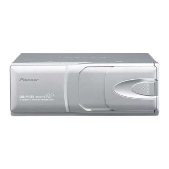
Pioneer CDX-P1270 Formation à l'entretien et à la réparation - Page 40
Parcourez en ligne ou téléchargez le pdf Formation à l'entretien et à la réparation pour {nom_de_la_catégorie} Pioneer CDX-P1270. Pioneer CDX-P1270 50 pages. Multi-compact disc player
Également pour Pioneer CDX-P1270 : Manuel du propriétaire (4 pages), Manuel du propriétaire (4 pages), Manuel du propriétaire (4 pages), Manuel du propriétaire (18 pages)

- 1. Table of Contents
- 1. 1 Safety Information
- 2. 2 Exploded Views and Parts List
- 3. 3 Block Diagram and Schematic Diagram
- 3. CD Mechanism Module
- 4. 4 Pcb Connection Diagram
- 5. 5 Electrical Parts List
- 6. 6 Adjustment
- 7. 7 General Information
- 7. Diagnosis
- 7. Test Mode
- 7. Disassembly
- 7. Connector Function Description46
- 7. Operational Flow Chart
- 8. 8 Operations and Specifications
CDX-P1270
7. GENERAL INFORMATION
7.1 DIAGNOSIS
7.1.1 TEST MODE
- Error Messages
If a CD is not operative or stopped during operation due to an error, the error mode is turned on and cause(s) of the
error is indicated with a corresponding number. This arrangement is intended at reducing nonsense calls from the
users and also for facilitating trouble analysis and repair work in servicing.
(1) Basic Indication Method
1) When SERRORM is selected for the CSMOD (CD mode area for the system), error codes are written to DMIN (min-
utes display area) and DSEC (seconds display area). The same data is written to DMIN and DSEC. DTNO remains
in blank as before.
2) Head unit display examples
Depending on display capability of LCD used, display will vary as shown below. xx contains the error number.
8-digit display
ERROR–xx
* When the system is manufactured for an OEM basis, the error display will be configured according to the customer
specification.
(2) Error Code List
Code Class
Displayed error code Description of the code and potential cause(s)
10
Electricity
Carriage Home NG
11
Electricity
Focus Servo NG
12
Electricity
Spindle Lock NG
Subcode NG
RF AMP NG
17
Electricity
Setup NG
30
Electricity
Search Time Out
A0
System
Power Supply NG
A1
System
Mechanism power
failure
40
6-digit display
ERR–xx
OR
Err–xx
CRG can't be moved to inner diameter.
CRG can't be moved from inner diameter.
→ Failure on home switch or CRG move mechanism.
Focusing not available.
→ Stains on rear side of disc or excessive vibrations on REWRITABLE.
Spindle not locked. Sub-code is strange (not readable).
→ Failure on spindle, stains or damages on disc, or excessive vibrations.
A disc not containing CD-R data is found. Turned over disc are found,
though rarely.
→ Failure on home switch or CRG move mechanism.
An appropriate RF AMP gain can't be determined.
→ CD signal error.
APC protection doesn't work. Focus can be easily lost.
→ Damages or stains on disc, or excessive vibrations.
Failed to reach target address.
→ CRG tracking error or damages on disc.
Power (VD) is ground faulted.
→ Failure on SW transistor or power supply (failure on connector).
Mechanism elevation reference voltage is out of
prescription.
→EREF adjustment VR and/or power abnormal.
4-digit display
E–xx
