DINA DN3PS2 Manuel d'instruction original - Page 9
Parcourez en ligne ou téléchargez le pdf Manuel d'instruction original pour {nom_de_la_catégorie} DINA DN3PS2. DINA DN3PS2 12 pages. Standstill monitoring for one and three phases motors without sensor system
Également pour DINA DN3PS2 : Manuel d'instruction original (16 pages)
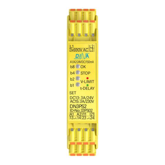
DN3PS2
Original Betriebsanleitung
Überwachung einer Schutzhaube
• Bei Auswahl Betriebsart FA1 ist die Überwachung
ständig aktiv.
• Die Schutzeinrichtung wird nur bei erkanntem Still-
stand entriegelt.
1) Not-Halt
2) Bearbeitungsanlage
3) Schutzhaube
4) Haube offen/ geschlossen
5) Werkzeug
6) Motoreinspeisung
7) Motor
8) EMK-Sensorleitung
9) Schutzhaubenschalter
10) Schutzhaubenfreigabe
Stillstandsüberwachung
• Anschluss von I11 und I21 an 24V DC über den Schutz-
einrichtungs-schalter deaktiviert die
Überwachung bei geschlossener Schutzhaube.
• Die Ausgangskontakte sind dauerhaft geschlossen
und die LED STOP leuchtet grün.
• Ein Öffnen der Schutzhaube bewirkt den Wechsel zu
Betriebsart FA1.
Eine Bewegung des Antriebs löst die Not-Halt Funktion
•
aus.
DN3PS2
Betriebsspannung
Power supply
24V DC
24V DC
1
NC
8
6
2
4
3
5
7
Betriebsspannung
Power supply
24V DC
1
NC
8
6
24V DC
2
4
3
5
7
Stand: 29.09.2017
Original instruction manual
Safety cover monitoring
• The monitoring is active during the function mode FA1.
• The safety cover is only unlocked if the drive is in
standstill.
1) Emergency stop
2) process unit
3) safety cover
4) cover open/ closed
5) tool
6) drive power supply
7) drive
8) EMF-Sensor wire
9) safety cover switch
10) safety cover enabling
OK
b8
A1
A2
Stop
b4
b2
b1
L1
SET
L2
Parameter
L3
9
I11
I21
10
DN3PS2
Standstill monitoring
• The connection of I11 and I21 via the switch of the safe-
ty cover to 24V DC deactivates the monitoring during
closed safety cover.
• The output contacts are permanently closed and the
LED STOP illuminates green.
• An opening of the safety cover activates the function
mode FA1.
An emergency stop function happens if the drive
•
moves
OK
b8
A1
Stop
A2
b4
b2
b1
L1
SET
L2
Parameter
L3
9
I11
I21
10
DN3PS2
Seite 9 von 12
Date: 2017-09-29
13
14
24V
DC
23
24
13
14
24V
DC
23
24
Page 9 of 12