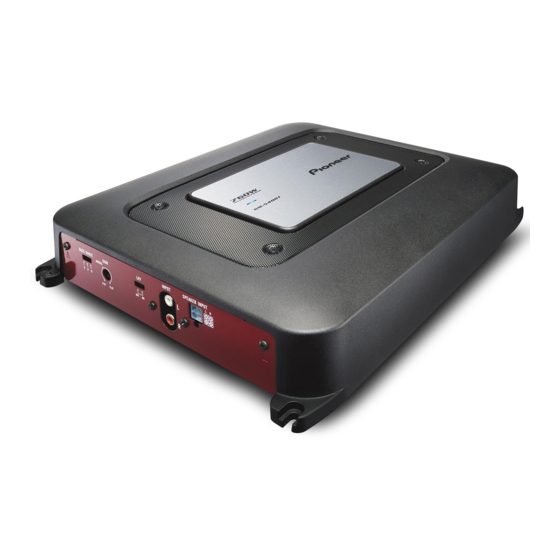
Pioneer GM5400T - Bridgeable Amplifier Manuel du propriétaire - Page 12
Parcourez en ligne ou téléchargez le pdf Manuel du propriétaire pour {nom_de_la_catégorie} Pioneer GM5400T - Bridgeable Amplifier. Pioneer GM5400T - Bridgeable Amplifier 41 pages. Bridgeable two-channel power amplifier
Également pour Pioneer GM5400T - Bridgeable Amplifier : Manuel du propriétaire (48 pages), Manuel du propriétaire (17 pages), Manuel du propriétaire (17 pages), Manuel d'entretien (29 pages)

Appendix
Additional information
Specifications
GM-5400T
Power source ............................. 14.4 V DC (10.8 V to 15.1 V
Grounding system ................... Negative type
Current consumption ............ 30 A (at continuous power,
Average current drawn ......... 10 A (4 W for two channels)
Fuse ................................................ 30 A × 2
Dimensions (W × H × D) ... 265 mm × 62 mm × 346
Weight .......................................... 3.8 kg (8.4 lbs)
Maximum power output ....... 250 W × 2 (4 W) / 760 W × 1
Continuous power output ... 125 W × 2 (at 14.4 V, 4 W, 20
Load impedance ...................... 4 W (2 W to 8 W allowable)
Frequency response ............... 10 Hz to 50 kHz (+0 dB, –1
Signal-to-noise ratio ............... 95 dB (IHF-A network)
Distortion ..................................... 0.03 % (10 W, 1 kHz)
Separation .................................. 70 dB (1 kHz)
Low pass filter:
Cut off frequency ........... 80 Hz
Cut off slope ..................... –12 dB/oct
Bass boost:
Frequency .......................... 50 Hz
Level ..................................... 0 dB/6 dB/12 dB
Gain control:
RCA ...................................... 200 mV to 6.5 V
Speaker .............................. 0.8 V to 26 V
Maximum input level / impedance:
RCA ...................................... 6.5 V / 22 kW
Speaker .............................. 26 V / 90 kW
12
En
allowable)
4 W)
19 A (4 W for one channel)
mm
(10-3/8 in. ×2-1/2 in. × 1 ft.
2 in.)
(Leads for wiring not in-
cluded)
(4 W)
Hz to 20 kHz 0.2% THD)
380 W × 1 (at 14.4 V, 4 W, 20
Hz to 20 kHz 0.8% THD)
190 W × 2 (at 14.4 V, 2 W, 20
Hz to 20 kHz 0.8% THD)
(Bridge connection: 4 W to 8
W allowable)
dB)
CEA2006 Specifications
Power output ............................. 125 W RMS × 2 Channels
S/N ratio ....................................... 75 dBA (reference: 1 W into
GM-3400T
Power source ............................. 14.4 V DC (10.8 V to 15.1 V
Grounding system ................... Negative type
Current consumption ............ 15 A (at continuous power,
Average current drawn ......... 4 A (4 W for two channels)
Fuse ................................................ 25 A × 1
Dimensions (W × H × D) ... 263 mm × 61 mm × 206
Weight .......................................... 2 kg (4.4 lbs)
Maximum power output ....... 120 W × 2 (4 W) / 350 W × 1
Continuous power output ... 60 W × 2 (at 14.4 V, 4 W, 20
Load impedance ...................... 4 W (2 W to 8 W allowable)
Frequency response ............... 10 Hz to 50 kHz (+0 dB, –1
Signal-to-noise ratio ............... 95 dB (IHF-A network)
Distortion ..................................... 0.01 % (10 W, 1 kHz)
Separation .................................. 70 dB (1 kHz)
(at 14.4 V, 4 W and ≦ 1 %
THD+N)
380 W RMS × 1 Channels
(at 14.4 V, 4 W BRIDGE and
≦ 1 % THD+N)
190 W RMS × 2 Channels
(at 14.4 V, 2 W and ≦ 1 %
THD+N)
4 W)
allowable)
4 W )
7.8 A (4 W for one channel)
mm(10-3/8 in. × 2-3/8 in. ×
8-1/8 in.)
(Leads for wiring not in-
cluded)
(4 W)
Hz to 20 kHz 0.2% THD)
175 W × 1 (at 14.4 V, 4 W, 20
Hz to 20 kHz 0.8% THD)
85 W × 2 (at 14.4 V, 2 W, 20
Hz to 20 kHz 0.8% THD)
(Bridge connection: 4 W to 8
W allowable)
dB)
