Ariston STI 210 INDIRECT Manuel de l'utilisateur - Page 3
Parcourez en ligne ou téléchargez le pdf Manuel de l'utilisateur pour {nom_de_la_catégorie} Ariston STI 210 INDIRECT. Ariston STI 210 INDIRECT 16 pages. Unvented hot water storage cylinders
Également pour Ariston STI 210 INDIRECT : Manuel d'instructions d'installation (20 pages), Instructions pour le manuel d'installation (24 pages)
The Comfort is supplied with the following;
One large box containing;
1) The unit with factory fitted Temperature & Pressure Relief Valve.
2) Factory fitted Immersion Heater (Dry pocket).
3) Factory fitted Cylinder Thermostat.
4) Feet x 3.
One small box containing;
1) Unvented control pack (Expansion vessel, 2 piece Cold Water Combination Valve, Tun Dish, Drain Cock and Motorised
Valve).
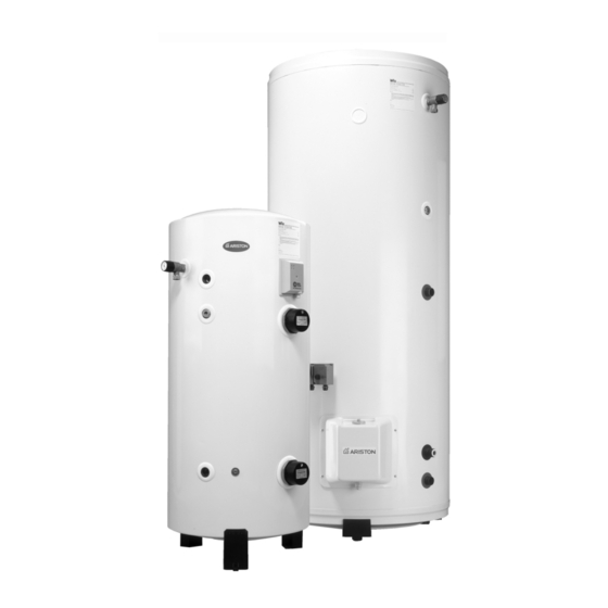
The high capacity floor-standing range (300, 500 litre models), which are supplied as the following;
One large box containing;
1) The unit
2) Factory fitted Temperature & Pressure Relief Valve (300 litre models only).
3) Factory fitted Immersion Heater(s)
4) Factory fitted Cylinder Thermostat.
5) Feet x 3.
One small box containing;
1) Unvented control pack (Expansion vessel, 2 piece Cold Water Combination Valve, Tun Dish, Drain Cock and Motorised
Valve) (500 litre model 1" Temperature & Pressure Relief Valve).
HOW THE HEATER WORKS
The Immersion Heater(s) are connected through a thermostat which senses the water temperature. The operating
temperature can be pre-set by adjusting the spindle in the head of the thermostat. In addition to the thermostat there is a
Thermal Cut-out incorporated if the thermostat fails and the water temperature rises too high. Once the cut-out operates it
can only be re-set manually after the fault has been rectified.
Indirect models have dual thermal controls. In addition to the above there is a separate Cylinder Thermostat and Thermal
Cut-out for controlling the indirect circuit. Again the Thermal Cut-out operates if the Cylinder Thermostat fails, by
disconnecting the live feed (call for hot water) from the programmer.
Floor-standing models have Magnesium Anodes provided to prevent corrosion of the water cylinder tank. Wall-hung units
have a single Magnesium Anode.
The factory fitted Temperature & Pressure Relief Valve at the top of the cylinder is a safety device to back-up the
Thermostat(s) and Thermal Cut-out(s). It works by sensing an excess in water temperature or pressure and releasing the
hot water into a Discharge Tundish and drain.
The cylinder will only work in the vertical position. The inlet pipe needs to deliver cold water to the bottom of the tank. When
water is heated it expands. To accommodate this increase in volume an Expansion Vessel is provided. A Cold Water
Combination Valve is also provided in two pieces, loose jointed for ease of installation. These comprise a Combined Line
Strainer/Pressure Reducing Valve and Core Non Return Valve/Expansion Relief Valve.
The Strainer prevents any debris entering the other controls. The Pressure Reducer ensures the correct operation of the
Expansion Vessel, and prevents any damage to the control valves through too great a pressure.
The Non-Return Valve ensures the water expansion is forced into the Expansion Vessel and prevents contamination of the
mains cold water supply. The Expansion Relief Valve will discharge expanded water to the Discharge Tundish if the
Expansion Vessel fails.
COLD WATER SUPPLY
It is important to ensure that the cold water main is capable of supplying the increased demand which will be imposed on it.
- 4 -
Hot and cold water are both drawn off the same source of supply. Remember, there will not be a storage tank to help
compensate for variations in the demand on the system.
A minimum pressure of approximately 1.5 bar and 20 litres per minute is required for satisfactory operation. 85% of UK
dwellings have a mains pressure above 2.0 bar.
THE MAINS WATER SUPPLY MUST NOT EXCEED 12 BAR
SITING AND FIXING
The cylinder may be installed at any convenient position, as it is connected to the mains cold water supply, it is equally
effective on any floor.
However, do not install the unit in premises which may be subject to freezing. Ensure that the floor load bearing strength is
adequate to take the weight of the cylinder when full of water (see table 1).
The ST50, ST80 and ST100 models are wall mounted. All other models are free standing. These are supplied with feet
which are attached to the heater via self tapping screws which are also supplied. All units must be installed in the
VERTICAL POSITION.
For maintenance purposes leave at least 500 mm free space in front of the unit, for access to electrical components,
immersion heater(s) and magnesium anodes.
CONNECTION OF MAINS WATER SUPPLY
For Contract & Comfort models:
On the front of the unit there is a label to identify the connection ports. Please check this before making any connection
to the unit.
For units up to 300 litres it is recommended that all mains cold water supply pipe work is a minimum of 22mm, with the
exception of model ST50 where 15mm can be used. For 500 litre models the supply should be 28mm. An Isolating Valve
should be installed between the cold water supply and the cylinder for servicing. ALL PIPEWORK MUST BE FLUSHED TO
AVOID DAMAGE TO THE CONTROL VALVES.
Please refer to figs. 1, 2 , 3, 3, 3, 3, 3 for a suggested installation layout.
A
B
C
D
COLD WATER COMBINATION VALVE
The Cold Water Combination Valve can be connected either close by the unit or alternatively it may be installed in a remote
position from the unit as there is no requirement to site it in close proximity to the cylinder. This allows a flexible and
convenient installation. However, it is important to note allowances for the discharge pipe work from the Expansion Relief
Valve must be accounted for.
A Balancing Port is supplied on the 22mm (for units above 50 litres) valve allowing balanced cold water supply to the rest of
the building giving excellent results with mixer and shower valves. If the facility is not needed a plug is supplied. Refer to fig.
4
Although this facility is not built into the 15mm valve (supplied with Contract ST50), a Tee Piece may be inserted between
the two components giving the same results. Refer to fig. 5
CONNECTION TO SERVICES
Again it is recommended that a 22mm pipe run should supply the outlets throughout the building, especially to baths and
showers. Short runs of 15mm pipe may be used to connect basins and sinks.
- 5 -