Cal Test Electronics CT3684 Manuel de l'utilisateur - Page 8
Parcourez en ligne ou téléchargez le pdf Manuel de l'utilisateur pour {nom_de_la_catégorie} Cal Test Electronics CT3684. Cal Test Electronics CT3684 17 pages.
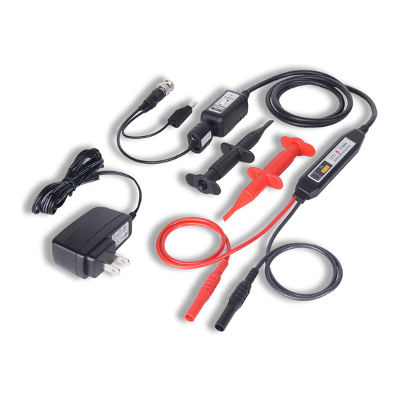
3.3 Inspection Procedure
1.
Connect the BNC output connector to the vertical input of
the oscilloscope.
2.
Power on the probe.
3.
Set the oscilloscope input to DC coupling and 1V/div. Center
the trace on the display.
4.
Set the attenuation setting on the oscilloscope to match the
probe 10x (CT3684) and 100x (CT3685).
5.
Connect the hook probes to the leads.
6.
Connect the black hook probe to the ground connection on
the oscilloscope and the red hook probe to the test signal on
the oscilloscope (1 kHz for example).
7.
A wave matching the test signal should display on the
screen of the oscilloscope and this means this probe is
working properly.
3.4 Getting Started
1.
Connect the hook probes to the leads.
2.
Connect the probe to the oscilloscope with the BNC cable.
When using a portable or ungrounded oscilloscope, connect
the output ground lead to ground.
3.
Switch the probe "ON."
4.
Set the attenuation setting on the oscilloscope to match the
probe 10x (CT3684) and 100x (CT3685).
5.
Use the hook probes to contact the circuit to be tested.
CAUTION
This probe is used to carry out differential measurements between
two points on the circuit under test. This probe is not for electrically
insulating the circuit under test and the measuring instrument.
800-572-1028
caltestelectronics.com
7