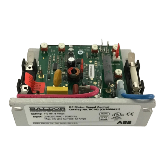
ABB Baldor BC141 Manuel d'installation et d'utilisation - Page 9
Parcourez en ligne ou téléchargez le pdf Manuel d'installation et d'utilisation pour {nom_de_la_catégorie} ABB Baldor BC141. ABB Baldor BC141 20 pages. Dc control

The AC Line Fuse protects the control against catastrophic failure. If the AC Line Fuse blows, the control is
miswired, the motor is shorted or grounded, or the control is defective.
Fuse holders and fuses not supplied with BC142-5.
Note: Fuse each AC line conductor that is not at ground potential.
Figure 2-2 Control Layout & General Connection Diagram (Catalog No. BC142-6 Shown)
25 Amp*
Line Fuse
Factory Installed
Enable S witch
(C lose to R un)
(Open to S top)
AC Line
Main S peed Potentiometer
Input
* Fuse holders and fuses not supplied with B C 142-5.
AC Line Connection
WARNING: Electrical shock can cause serious or fatal injury. Be sure that all power is disconnected and there is
no voltage present from this equipment or equipment to which it is or will be connected. Electrical
shock can cause serious or fatal injury. Only qualified personnel should attempt the installation and
start-up procedures.
The control can be turned "on" and "off" using the AC line disconnect. Auto-Inhibit® circuitry automatically
resets critical components each time the AC line is interrupted. This, along with Acceleration Start and CL,
provides a smooth start each time the AC line is applied.
Connect the AC line to Terminals L1 (Line Fuse)* and L2, Figure 2-2. For 115VAC connect neutral to L2.
Catalog No. BC141 operates on 115 Volt AC line input only.
Catalog No. BC142 operates on 208/230 Volt AC line input only.
Catalog BC142-5 and BC142-6 operates on 115 Volt AC line input when Jumper J1 is set to the 115 position
and operates on 208/230 Volt AC line input when Jumper J1 is set to the 230 position (factory setting).
* Fuse holders and fuses not supplied with BC142-5.
Note: When using a step-down transformer (460 Volts AC to 230 Volts AC), be sure the output current
rating of the transformer is at least 3 times the current rating of the motor. Do not switch the
primary side of the transformer to disconnect power or catastrophic failure can result.
Always disconnect the control from the secondary side of the transformer.
Ground Connection
Connect the ground wire (earth) to the control chassis.
2-2
B lue
L1
L2
DEC EL
T
AC C EL
J 1
P2
I1
P3
P1
MIN
MAX
High
Wiper
Low
(Front View)
(C lose to S top)
A+
F+
B
J 2
C L
I2
C L
+
-
Inhibit S witch
Motor Field
(Open to R un)
(S hunt Motors Only)
Plug-In
R ed
Horsepower R esistor®
S upplied S eparately
F-
Armature Fuse*
S upplied S eparately
Plug-In Horsepower
R esistor® and
Armature Fuse Kit
A-
supplied separately
S ee S ection 9.
IR
+
+
M
-
-
Motor Armature
DC Tach-Generator
(S et J 2 to "T" Position)
7V
G
1000
MN704
