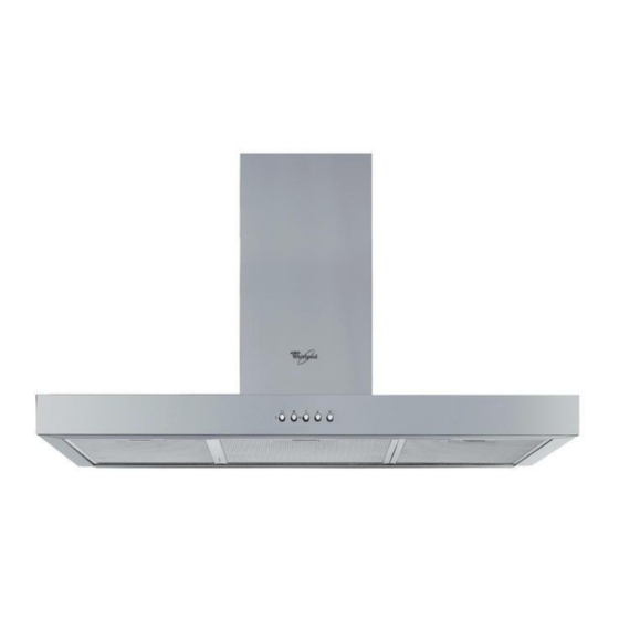
Whirlpool AKR902TBIX Manuel d'utilisation - Page 15
Parcourez en ligne ou téléchargez le pdf Manuel d'utilisation pour {nom_de_la_catégorie} Whirlpool AKR902TBIX. Whirlpool AKR902TBIX 47 pages. 90cm t-box rangehood
Également pour Whirlpool AKR902TBIX : Manuel d'utilisation (9 pages)

The hood is designed for use in "Extractor version" or in "Filter version".
Extractor Version
Fumes are extracted and expelled to the outside through an exhaust pipe (not supplied) fixed to the hood exhaust pipe
connector (Fig.d, Fig.e).
Depending on the exhaust pipe purchased, provide for suitable fixing to the exhaust pipe connector.
Important: If already installed, remove the carbon filter/s.
Filter Version
Air is filtered through the carbon filter/s and recycled into the surrounding environment.
Important: check that air recirculation is facilitated (to this end, carefully follow the instructions given in the installation
handbook)
Important! If the hood does not have a carbon filter/s, it/they must be ordered and fitted before use.
Preliminary information for installing the hood:
Expansion plugs are provided to secure the hood to most types of ceilings. However, a qualified technician is needed to make
sure that the plugs are suitable for your ceiling. The wall/ceiling must be strong enough to take the weight of the hood. Remove
the grease filters
Pre-assembly of the electrical connection box:
(a.) remove the screws and washers on the extractor unit and remove the adhesive tape fixing the box to the extractor unit,
(b.) position the electrical connection box above the extractor unit, (c.) secure with 2 Ø 3.5 x 9.5 screws and 2
Ø 14 x 12 washers (previously removed).
Using a pencil, draw the centre line on the wall up to the ceiling (Fig.1).
1.
2. If necessary, cut the drilling template according to the width of the hood.
Apply the drilling template to the wall: the vertical centre line printed on the drilling template must match the centre line
3.
drawn on the wall and, depending on the height of the hood, the lower horizontal edge of the drilling template must match
the lower edge of the hood.
Drill as shown on the template, insert the wall plugs and screw in the top 2 screws, leaving a space of approx. 1 cm
4.
between the screw head and the wall.
Note: Drill all the holes indicated on the template: the top 2 holes are for hanging the hood and the bottom holes are for
fixing it securely to the wall.
Fit the flue support bracket "G" (Fig.1) to the wall and against the ceiling. Use the support bracket as drilling template (if
5.
present, the small slot on the support must match the line drawn on the wall) and mark 2 holes with the pencil, drill the
holes and finally insert 2 plugs.
Fix the flue support bracket to the wall with 2 screws.
6.
Remove the drilling template from the wall and hang the hood on the 2 top screws (Fig.1).
7.
Screw in the bottom screws (and washers!) to fix the hood securely in place (COMPULSORY!!).
8.
After checking the alignment of the hood, TIGHTEN ALL THE SCREWS - top and bottom.
Note: the bottom fixing points are visible upon removal of the grease filters.
Connect an exhaust pipe to the exhaust pipe connector located above the extraction motor unit.
9.
For extractor operation, connect the other end of the exhaust pipe to the home discharge device.
For filter operation, fix the deflector F to the flue support bracket G and connect the other end of the exhaust pipe to the
deflector collar F (Fig.1).
Make all necessary electrical connections.
10.
Fit the flues over the extractor unit, engaging them in their seat above the hood.
11.
Slide the top section of the flue upwards and secure it with 2 screws (11a) to the flue support bracket "G" (11b).
12.
Refit the grease filters and check for correct hood operation.
5019 318 33292
D
GB
F
NL
E
P
I
GR
