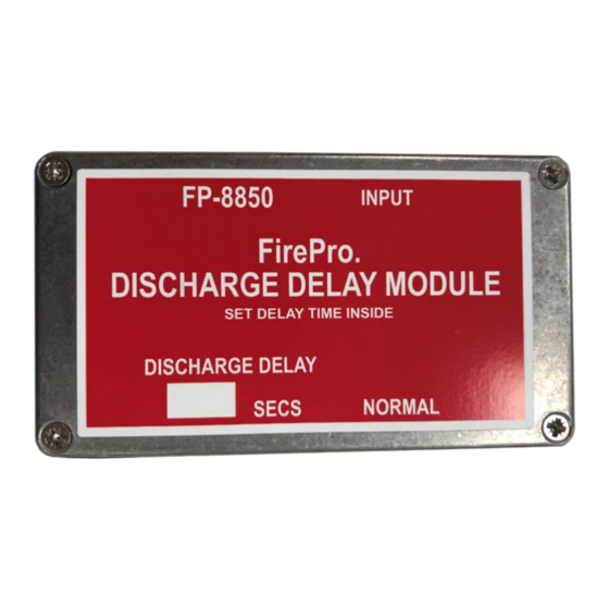
FirePro FP-08850 Manuel - Page 6
Parcourez en ligne ou téléchargez le pdf Manuel pour {nom_de_la_catégorie} FirePro FP-08850. FirePro FP-08850 10 pages. Discharge delay module

Installation
4
1. FirePro generators must remain disconnected until system is completed and fire control
panel is no longer in a fault or alarm condition. The FirePro Universal Test Lamp (P/N FP-
08800) can be used to take the panel out of a fault condition.
2. Ensure programming of fire control panel is set for extended discharge. (See FP-08450 or
FP-08451 Manual)
3. Identify the FirePro generators to be activated in the initial discharge. The cable to these
should be connected in series to the "Normal" output on the module (marked yellow 1),
using the FP-08919 Splitter Lead where necessary. A Universal Test Lamp (P/N FP-08800)
should be connected at each point where a FirePro generator has been installed.
4. If only using the "Delayed Discharge" output, the 3k3Ω End-of-line resistor should be
terminated into the supplied 3 pin deutsch plug and then connected to the "Normal" output
on the module (marked yellow 1).
heatshrink, and the heatshrink crimped, to avoid ingress of water into the circuit.
5. If using multiple modules, the next module should now be connected to the "Discharge
Delay" output on the first module and step 2 repeated.
6. Identify the FirePro generators to be activated in the secondary discharge. The cable to
these should be connected in series to the "Discharge Delay" output on the module (marked
yellow 2), using the FP-08919 Splitter Lead where necessary. A Universal Test Lamp (P/N
FP-08800) should be connected at each point where a FirePro generator has been installed.
7. The settings of the Discharge Delay Module can now be programmed to suit vehicle or site
specific requirements. (See 6. Programming)
The end-of-line plug should then be covered in
