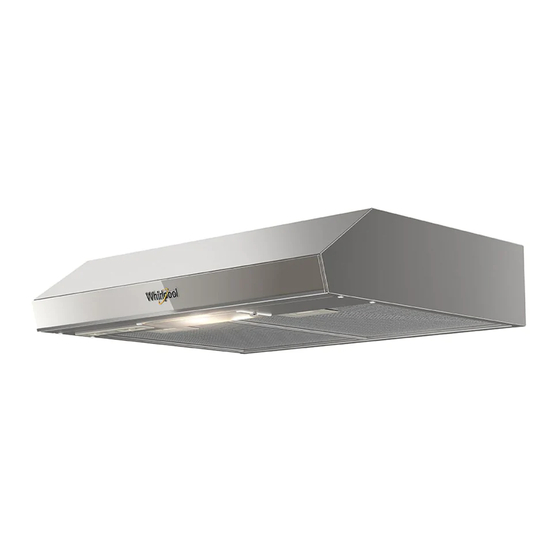
Whirlpool WH6010S Instructions d'installation et manuel d'utilisation et d'entretien - Page 3
Parcourez en ligne ou téléchargez le pdf Instructions d'installation et manuel d'utilisation et d'entretien pour {nom_de_la_catégorie} Whirlpool WH6010S. Whirlpool WH6010S 15 pages. 23.6", 30", and 31.5" (60 cm, 76 cm, and 80 cm)

Tools and Parts
Gather all the required tools and parts before
commencing the installation.
Read and follow the instructions provided with any of
the tools listed here.
Parts Supplied
Remove the parts from the package. Make sure that
no parts are missing.
(4) 4.5 x 13 mm mounting screws (Under-cabinet
installation)
(4) 5 x 45 mm mounting screws (Wall-mounted)
(4) 8 x 40 mm wall anchors (Wall-mounted)
Tools Needed
Drill
11⁄4" (3.0 cm) bit
1/8" (3.0 mm) bit for pilot holes
Pencil
Measuring tape or ruler
Flat-blade screwdriver
Phillips screwdriver
Jigsaw or keyhole saw
Parts Needed
For cabinets with embedded bases:
Two 2" (5.1 cm) strips of wood. Length is
determined by gap size.
Four flat-head screws for wood or screws for metal
with clamps and nuts (to secure the packing strips).
Product Dimensions
5
Location Requirements
IMPORTANT: Observe all applicable codes and
regulations.
It is the installer's responsibility to comply with
installation clearances specified on the
model/serial/rating plate.
The model/serial/rating plate is located on the
inside left wall of the hood.
Hood location should be away from strong draft
areas, such as windows, doors and strong heating
vents.
The cabinet opening dimensions shown must be
used.
The dimensions given provide minimum clearance.
Consult the cooktop/range manufacturer's
installation instructions before making any
cutouts.
All openings in the ceiling or wall where the hood is
to be installed must be sealed.
These range hoods are factory set for recirculating
installations.
Before Installing
Remove the white film from the hood.
Remove the blue film from the aluminum filters.
Remove any pac king items.
Electrical Wiring
6
