Direct Healthcare Group Dyna-Form Mercury Advance Manuel de l'utilisateur - Page 7
Parcourez en ligne ou téléchargez le pdf Manuel de l'utilisateur pour {nom_de_la_catégorie} Direct Healthcare Group Dyna-Form Mercury Advance. Direct Healthcare Group Dyna-Form Mercury Advance 16 pages.
Également pour Direct Healthcare Group Dyna-Form Mercury Advance : Manuel de l'utilisateur (9 pages)

4. Installation
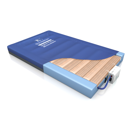
4.1 Mattress (This is the applied part type BF)
Place the Dyna-Form® Mercury Advance Trolley Mattress directly on to the bed platform ensuring
that the Blue multi-stretch waterproof cover is on top and that the umbilical hose is located at
the left hand corner at the foot end of the bed. Note: The umbilical hose can be located inside the
cover under the "Open Here for Air Inlet" printed in the bottom left hand corner of the mattress.
Cover the Mattress with a loose fitting sheet.
Static Mattress Use
The Dyna-Form® Mercury Advance Trolley Mattress can be used as a pressure reducing mattress
for patients at High Risk of pressure ulcer damage without the need to attach the pump.
Alternating Mattress Use
If / When required, the Dyna-Form® Mercury Advance Trolley Mattress can be used as an
alternating mattress system by attaching the Dyna-Form® Mercury Advance Trolley Power Unit
(Pump) system.
No other system should be attached to the mattress as the design settings and internal
air pressure properties of the Dyna-Form® Mercury Advance Trolley Power Unit (Pump) are
specific to this mattress only.
The Dyna-Form® Mercury Advance Trolley is a replacement mattress system and should NOT be
placed on top of any existing mattress.
The startup time from static to dynamic mode is immediate.
4.2 Power Unit (Pump)
Hang the Power Unit (Pump) onto the footboard. The mounting hooks swivel to suit the thickness
of the footboard or rail. Connecting the Umbilical Hose to the Power Unit (Pump), place the 3-pin
electrical plug into the wall outlet and switch on:
(a) Open the zip located at the bottom left hand side of the mattress and pull out the Blue Umbilical hose.
(b) Attach the Blue Umbilical Hose to the Power Unit (Pump) by connecting the air connector
at the end of the Umbilical Hose to the air inlet connector at the bottom left hand side of the
pump. Ensure that the Red CPR Release button is located on top of the Air Inlet connector after
connection is complete.
(c) Re-close the zip as far as possible without clamping the Blue Umbilical Hose to ensure the
mattress and air cells are sealed within the cover.
(d) Shut down is the reverse of items a, b & c above.
5. Operation
Attach the mains cable to the pump by inserting the "kettle" type connector into the recess
located on the left hand side of the pump. The mains cable has been designed specifically as a
removable part to aid in easy replacement should it become damaged in use.
The mains plug should be turned off and removed from wall socket as a means of isolation.
Plug the mains cable into a suitable 230v mains socket and switch on the Power Unit using the
on/off switch.
After the pump has been turned on both the "High "and the "Low" lights will flash together
intermittently until the pump has attained its initial operating pressure. Once the pump has
attained its initial operating pressure the "Low" light will stay on constantly and the mattress is
ready for use.
U S E R M A N U A L
D I R E C T H E A L T H C A R E G R O U P . C O M
7
