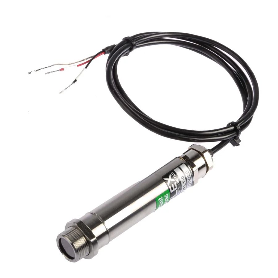
Calex PUA5 GLT Series Connexion et configuration
Parcourez en ligne ou téléchargez le pdf Connexion et configuration pour {nom_de_la_catégorie} Calex PUA5 GLT Series. Calex PUA5 GLT Series 2 pages. Electronics two-wire 4-20 ma output sensor with a drr245 controller

Tel: +44 (0)1525 373178/853800, Lo-call: 0845 3108053, Fax: +44 (0)1525 - 851319
Connecting sensor and power:
1. Attach power supply wires to pin 23 & 24
2. Attach sensor wires:
For PyroCouple and PyroUSB sensors:
PWR + (Red) to pin 16
PWR - (Black) to pin 13
3. Turn on the power. The display flashes "E-05".
Entering configuration mode:
4. Press and hold SET for 5 seconds until the display shows "0000".
5. Enter the password. Default password is "1234":
Press UP to increase first digit to "1". Press SET.
Press UP twice to increase second digit to "2". Press SET.
Press UP three times to increase third digit to "3". Press SET.
Press UP four times to increase third digit to "4". Press SET.
The display shows first configuration parameter "c.out".
Inputting the sensor's temperature range:
6. Adjust the configuration parameters:
Press UP and DOWN to select a configuration parameter to adjust.
Hold SET and press UP and DOWN to change the value.
7. Change the value of parameter "Sen." to "4.20"
The controller now accepts the sensor's 4-20 mA input.
Registered Office: 20 Bridge Street, Leighton Buzzard, Beds, LU7 1AL
Registered Number: 3737294 England
E-mail: [email protected], Online: www.calex.co.uk
Connecting and Configuring
a Calex Electronics two-wire 4-20 mA output sensor
with a DRR245 Controller
PO Box 2, Leighton Buzzard
Bedfordshire, England LU7 4AZ
DRR245 - 4-20 mA Connection Instructions.doc-15:09-29/09/17
Continued...
1 of 2
