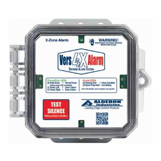
Alderon Industries VersAlarm 4X Manuel d'utilisation, d'entretien et d'installation - Page 3
Parcourez en ligne ou téléchargez le pdf Manuel d'utilisation, d'entretien et d'installation pour {nom_de_la_catégorie} Alderon Industries VersAlarm 4X. Alderon Industries VersAlarm 4X 6 pages. 2-zone outdoor
Également pour Alderon Industries VersAlarm 4X : Manuel d'utilisation, d'entretien et d'installation (3 pages)

VersAlarm
2-Zone | Outdoor Alarm System, Type 4X
Operation, Maintenance and Installation Manual
Installation
1. Prior to mounting the alarm panel, install the conduit connections
required per application. Open cover prior to step 2.
2. Determine the center hole locations, mark and drill out on the bottom of
the enclosure, separated by approximately two-inches. The size(s) will
depend on desired conduit fitting (maximum 0.75"). Place the conduit
fitting (Fig. 4A) in the drilled out hole and make sure it's secured. Then
install conduit (Fig. 4B) into the fitting.
Note: Seal all conduits to prevent moisture and gases from entering the enclosure
per local codes.
CAUTION: Nonmetallic enclosure does not provide grounding between conduit
connections. Use grounding bushings and jumper wires.
3. Determine the mounting location for the alarm panel, it's recommended
to use four (4) screws to properly mount the enclosure: top left, top right,
bottom left, and bottom right (Fig. 5A).
4. Hold the alarm panel in the desired mounting location, mark the drill
hole locations. Once marked, drill pilot holes for screws (not included)
and use wall mount anchors (not included) if necessary. Place alarm
panel in the mounting location, adjust until pilot holes are lined up with
the enclosure and fasten screws to secure the alarm panel in place.
Mounting Holes:
i.
Left to Right - 1.97" (center to center)
ii.
Top to Bottom - 5.37" (center to center)
Alarm Systems
Control Panels
Alderon Industries - Hawley, MN | 218.483.3034 | [email protected] | alderonind.com
4X
™
Float Switches
Leak Detection Systems
(Fig. 4)
4A
4B
(Fig. 5)
5A
5A
P/N: QSG00307_Rev01
Page 3 of 6
