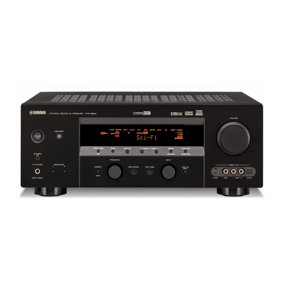
Yamaha htr-5890 Manuel d'entretien - Page 29
Parcourez en ligne ou téléchargez le pdf Manuel d'entretien pour {nom_de_la_catégorie} Yamaha htr-5890. Yamaha htr-5890 41 pages.

- 1. Table of Contents
- 2. Service Manual
- 3. Important Notice
- 4. To Service Personnel
- 5. Front Panel
- 6. Remote Control Panel
- 7. Rear Panels
- 8. Specifications
- 9. Internal View
- 10. Disassembly Procedures
- 11. Updating Firmware
- 12. Self Diagnosis Function (Diag)
- 13. Amp Adjustment
- 14. Display Data
- 15. IC Data
- 16. Remote Control
FAN DRIVE TEST
HIGH
FAN DRIVE TEST
MID
FAN DRIVE TEST
LOW
13. V CONV STATUS
The data received from the video conversion IC
(TA1270) is displayed.
LOW BYTE DATA
The status information of TA1270 is displayed in the
binary notation.
Horizontal lock judgment
0: LOCK
1: UN-LOCK
Vertical standard discrimination
0: STANDARD
1: NON-STANDARD
Vertical frequency
0: 50Hz
1: 60Hz
X'tal mode
00: −
01: 4.43
10: −
11: 3.58
Color system
00: B/W
01: SECAM
10: PAL
11: NTSC
Power ON reset
0: RESISTER PRESET
1: NORMAL
HIGH BYTE DATA
Not applied to this model.
14. IF STATUS (Input function status)
Using the sub-menu, the status data is displayed one
after another in the hexadecimal notation.
During signal processing, the status before execution
of this menu is maintained.
* Numeric values in the figure example are for
reference.
IS1-2 (Internal status):
Indicates the status information of the microprocessor.
<1st byte>
Digital input/output setting value
Upper 4 bits: REC OUT selected /
lower 4 bits: INPUT selected
Value
Choice
0
NONE
1
OPT A
2
OPT B
3
OPT C
4
OPT D
6
OPT F
8
COAX A
9
COAX B
A
COAX C
HTR-5890
5th byte
4th byte
3rd byte
2nd byte
1st byte
Preset name
V-AUX
CD
DVD
D-TV
CBL/SAT
CD
DVD
DVR/VCR2
29
