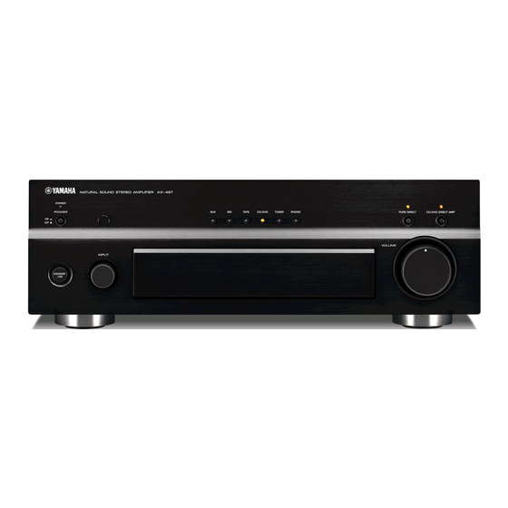
Yamaha AX-497 Manuel d'entretien - Page 12
Parcourez en ligne ou téléchargez le pdf Manuel d'entretien pour {nom_de_la_catégorie} Yamaha AX-497. Yamaha AX-497 36 pages. Stereo amplifier
Également pour Yamaha AX-497 : Manuel du propriétaire (23 pages), Manuel du propriétaire (24 pages)

- 1. Table of Contents
- 2. Important Notice
- 3. To Service Personnel
- 4. Impedance Selector
- 5. Remote Control Panel
- 6. Front Panel
- 7. Rear Panels
- 8. Specifications
- 9. Internal View
- 10. Disassembly Procedures
- 11. Adjustment
- 12. IC Data / Block Diagram
- 13. Pin Connection Diagram / Printed Circuit Board
- 14. Parts List
- 15. Exploded View
- 16. Remote Control Rax15
AX-397
QQ
3 7 63 1515 0
IC DATA
IC301 : M38503G4A-101FP (FUNCTION (1) P.C.B.)
8-bit Microprocessor
No.
Port
1
V
CC
2
V
REF
3
AV
SS
4
P4
/INT
/PWM
4
3
5
P4
/INT
/S
3
2
CMP2
TE
L 13942296513
6
P4
/INT
2
1
7
P4
/INT
1
0
8
P4
/CNTR
0
1
9
P2
/CNTR
//S
7
0
RDY1
10
P2
/S
6
CLK1
11
P2
/T
D
5
X
12
P2
/R
D
4
X
13
P2
3
14
P2
2
15
CNV
SS
16
P2
/X
1
CIN
17
P2
/X
0
COUT
18
/RESET
19
X
IN
20
X
OUT
21
V
SS
22
P1
/(LED
)
7
7
23
P1
/(LED
)
6
6
24
P1
/(LED
)
5
5
25
P1
/(LED
)
4
4
26
P1
/(LED
)
3
3
27
P1
/(LED
)
2
2
28
P1
/(LED
)
1
1
29
P1
/(LED
)
0
0
30
P0
(AN
)
7
8
31
P0
(AN
)
6
7
32
P0
(AN
)
5
6
33
P0
(AN
)
4
5
34
P0
//S
3
RDY2
www
35
P0
/S
2
CLK2
36
P0
/S
1
OUT2
37
P0
/S
0
IN2
38
P3
/AN
4
4
.
39
P3
/AN
3
3
40
P3
/AN
2
2
41
P3
/AN
1
1
42
P3
/AN
0
0
12
http://www.xiaoyu163.com
V
1
CC
V
2
REF
AV
3
SS
P4
/INT
/PWM
4
4
3
P4
/INT
/S
5
3
2
CMP2
P4
/INT
6
2
1
P4
/INT
7
1
0
P4
/CNTR
8
0
1
P2
/CNTR
/S
9
7
0
RDY1
P2
/S
10
6
CLK1
P2
/T
D
11
5
X
P2
/R
D
12
4
X
P2
13
3
P2
14
2
CNV
15
SS
P2
/X
16
1
CIN
P2
/X
17
0
COUT
RESET
18
X
19
IN
X
20
OUT
V
21
SS
Name
I/O
Function
MCU
Power Supply, +5V
MCU
AD Reference
MCU
AD Ground
PD
I
Power Down Detect
TPM/PD
I
Tape Monitor /Pure Direct SW
PS
I
SYSTEM Power SW
REM
I
Remote Control (Wake up)
PRINH
I
Release the Protection
CEI
O
Chip Enable (INPUT SEL)
CK
O
Clock
DATA
O
Data
TMO/DEST
O/I
Tape Monitor (397)/Destination Distinction (497)
VRUP
O
Motor Volume (UP)
VRDN
O
Motor Volume (DOWN)
CNV
MCU
Vss: when single chip mode is used, Vcc: when flash writing is used
SS
D43
I
AX-497/397 Detect
CDM
O
CD Direct Mute
MCU
Reset
MCU
Oscillator In
MCU
Oscillator Out
MCU
Ground
LEDA
O
LED (AUX)
LEDTP
O
LED (TAPE)
LEDM
O
LED (MD)
LEDC
O
LED (CD)
LEDT
O
LED (TUNER)
LEDP
O
LED (PHONO)
LSBY
O
LED (POWER)
LEDCDD
O
LED (CD DIRECT)
LEDTM/PD
O
LED (TAPE MONITOR/PURE DIRECT)
ENL
I
Rotary Encoder (Left)
ENR
I
Rotary Encoder (Right)
MUTE
O
Mute
CDD
I
CD Direct SW
PRI
I
Protection (Overload)
RYSP
O
Speaker Relay
x
ao
y
RYPS
O
Power Relay
PRDC
I
Protection (DC)
i
PRPS
I
Protection (Power Supply)
THMR
I
Protection (Temperature Detection)
THML
I
Protection (Temperature Detection)
REC
I
Rec Out Selector Detect
http://www.xiaoyu163.com
8
42
P3
/AN
0
0
41
P3
/AN
1
1
40
P3
/AN
2
2
39
P3
/AN
3
3
38
P3
/AN
4
4
37
P0
/S
0
IN2
36
P0
/S
1
OUT2
35
P0
/S
2
CLK2
34
P0
/S
3
RDY2
33
P0
/(AN
)
4
5
32
P0
/(AN
)
5
6
31
P0
/(AN
)
6
7
30
P0
/(AN
)
7
8
29
P1
/(LED
)
0
0
28
P1
/(LED
)
1
1
27
P1
/(LED
)
2
2
26
P1
/(LED
)
3
3
25
P1
/(LED
)
4
4
24
P1
/(LED
)
5
5
23
P1
/(LED
)
6
6
22
P1
/(LED
)
7
7
Q Q
3
6 7
1 3
u163
.
2 9
9 4
2 8
1 5
0 5
8
2 9
9 4
m
co
9 9
2 8
9 9
