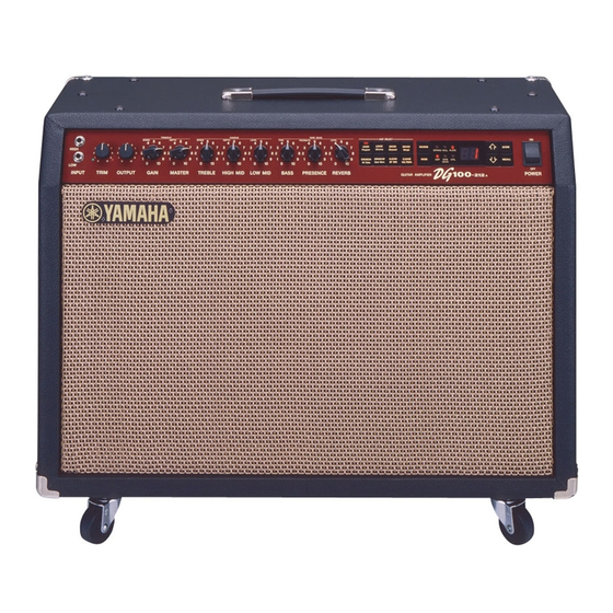
Yamaha DG100-212 Manuel d'entretien - Page 6
Parcourez en ligne ou téléchargez le pdf Manuel d'entretien pour {nom_de_la_catégorie} Yamaha DG100-212. Yamaha DG100-212 42 pages. Yamaha guitar amplifier owner's manual
Également pour Yamaha DG100-212 : Manuel du propriétaire (32 pages)

DG100-212
BLOCK DIAGRAM
6
DISASSEMBLY PROCEDURE
1.
Pre-Main Unit
1-1 Remove the four (4) screws marked [70A]. The
back board (U) can then be removed. (Fig. 1)
1-2 Remove the plug of the connector assembly
(speaker) located on the rear panel and the six
(6) screws marked [30A]. The pre-main unit can
then be removed by sliding it backward.(Fig. 1,
Fig. 2)
2.
Speakers
2-1 Remove the four (4) screws marked [70A]. The
back board (U) can then be removed. (Fig. 1)
2-2 Remove the four (4) screws marked [70B]. The
back board (L) can then be removed. (Fig. 1)
2-3 Remove the plug of the connector assembly
(speaker) located on the rear panel and the eight
(8) hexagonal nuts with flanges marked [60A].
The right and left speakers can then be removed.
(Fig. 1)
Connector assembly (speaker)
Pre-main unit
[60A] x 4
[70A]
[60A]
[70B]
Speakers
[60]:
Hexagonal Nut 5.0 x 35 MFC2BL
(EX000990)
[70]:
Oval Head Tapping Screw 4.0 x 30 MFC2BL
(EN240090)
(Fig. 1)
Back board (Upper)
[30A]
[70A]
[70B]
Pre-main unit
[30A]: Oval Head Screw 5.0 x 35 MFC2BL
(VP104600)
(Fig. 2)
