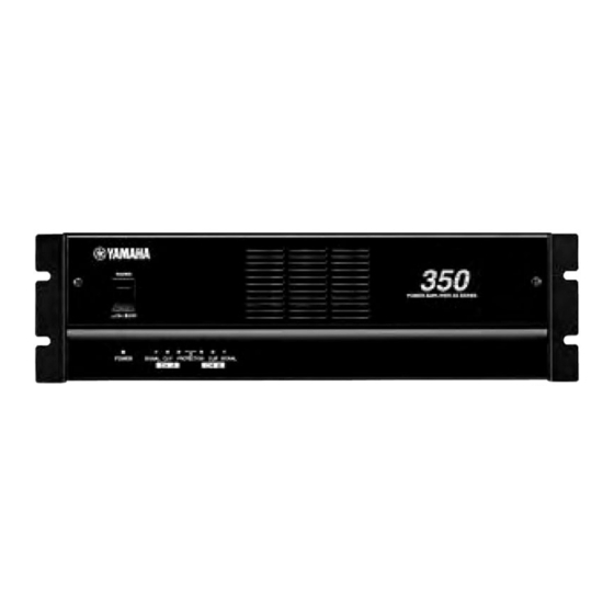
Yamaha XS250 Manuel d'entretien - Page 14
Parcourez en ligne ou téléchargez le pdf Manuel d'entretien pour {nom_de_la_catégorie} Yamaha XS250. Yamaha XS250 28 pages. Power amplifier
Également pour Yamaha XS250 : Manuel du propriétaire (15 pages)

XS250/350
7. Harmonic Distortion Test
When a high quality sine wave is applied at 20 Hz, 1 kHz or 20 kHz, the harmonic distortion should be as follows:
Power output level (4 ohm)
XS350
350 W + 350 W (33.7 dBu/ch)
XS250
250 W + 250 W (32.2 dBu/ch)
*This test should have been finished within 30 minutes.
8. Channel Separation Test
8-1 Apply a -5 dBu, 20kHz sine wave into the channel A.
8-2 Short the input for the channel B with a 600 ohm load.
8-3 Set the output of the channel A at a reference of 0 dB.
8-4 If channel B attenuator is set to the same as channel A, channel B output should be l
ess than -65 dB. (RL = 8 ohm)
9. Noise Test
9-1 Set the input attenuator to MAX.
9-2 Short the input with a 600 ohm load.
9-3 Measure at the output, noise level should be less than -65 dBm.
9-4 Set the input attenuator to "∞", noise level should be less than -70 dBu.
*Be careful that it is not affected by noise induced during this inspection.
10. Stability Test
When a rectangular wave 10 kHz, -10 dBu is applied to the input and a capacitor 10 pF–0.47 µF is connected with 4 ohm load resistor in
parallel, the overshoot and the ringing should be as follows.
Oversshoot:
Vp/Vo </= 1.8
Ringing: less than 5 waves
Next, when the 4 ohm load resistor is removed and the load is the capacitor 10pF–0.47 µF only, the overshoot and the ringing should be
as follows.
Oversshoot: Vp/Vo </= 2.5
Ringing:
fade away in less than 7 waves and no oscilation
11. Protection Circuitry Test
Check that the relay does not work when you apply a sine wave of +5.0 dBu (XS350), +3.0 dBu (XS250) at 10 Hz to the input and adjust
the input level to obtain a clipped output wave form.
Next, check that when you apply a sine wave of 1 Hz, 0.0 dBu to the input, the signal is cut off within 2 seconds, and the PROTECTION
indicator should light up.
Finally, check that when no signal is applied, the amplifier would resume to normal operation within 10 seconds.
12. PC Limiter Circuitry Test
Check that the OUTPUT should be as follows with an oscilloscope when a sine wave of 0 dBu (XS350), -1.5 dBu (XS250) at 1 kHz is
applied to the INPUT and the output is shorted with a 1 ohm load ( +/-5%). At this time, check the CLIP indicator lights.
Model
Output level
XS350
Vp-p </= 25V
XS250
Vp-p </= 20V
*This test should have been finished within 30 minutes.
14
THD
20 kHz
1 kHz
20 kHz
</= 0.1 %
</= 0.1 %
</= 0.1 %
</= 0.1 %
</= 0.1 %
</= 0.1 %
