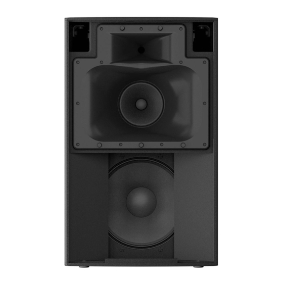
Yamaha DZR315 Manuel du propriétaire - Page 17
Parcourez en ligne ou téléchargez le pdf Manuel du propriétaire pour {nom_de_la_catégorie} Yamaha DZR315. Yamaha DZR315 31 pages. Powered loudspeakers/subwoofer
Également pour Yamaha DZR315 : Manuel du propriétaire (31 pages), Manuel du propriétaire (31 pages), Manuel du propriétaire (31 pages)

Installation Examples
CAUTION
• Before doing any installation or construction work, consult with your Yamaha dealer.
• The installation should be checked thoroughly at regular intervals. Some fittings may deteriorate over extended periods of
time due to wear and/or corrosion.
• When choosing the installation location, suspension wire and mounting hardware, make sure all are strong enough to
support the weight of the speaker.
• Make sure to take precautionary measures using wires to prevent the speaker from falling down in the event of an installa-
tion failure.
• When installing the wire to the wall, install it higher than the wire's attachment point on the speaker, with as little slack as
possible. If the wire is too long, and the speaker happens to fall, the wire may snap as a result of too much strain.
• Make sure to use eye bolts according to the standards and safety regulations in your area.
Yamaha cannot be held responsible for damage or injury caused by insufficient strength of the support structure or
improper installation.
Suspended Installation Using Eye Bolts
Attach commercially available long eye bolts (30–50 mm in
length) to the screw holes for the eye bolts (e on page 7). The
screw diameter for DZR315(-D), DZR15(-D), and DZR12(-D) is
M10, and the screw diameters for DZR10(-D) are M10 and M8.
Keep in mind that you will need two or more rigging points.
Securing the eye bolts
Insert the eye bolts through the washers when attaching
them.
NOTE
• The screw holes for eye bolts go through the cabinet wall.
• When using eye bolts, remove the flat-head screws tightened at
the time of factory shipment. When not using eye bolts, tighten
the flat-head screws in order to prevent air leaks.
Suspension angle
Make sure to use eye bolts within a range of 0 to 45 degrees from a right angle.
0°
45°
Suspended installation example
M10 eye bolt
Max. 45°
Side
Bottom
Max. 45°
Pullback point
Full range
Apply thread-
locking fluid
to the eye bolt
Rear
17
