Yamaha Electone HS-5 Manuel d'entretien - Page 10

Parcourez en ligne ou téléchargez le pdf Manuel d'entretien pour {nom_de_la_catégorie} Yamaha Electone HS-5. Yamaha Electone HS-5 43 pages. Serie hs monitor da studio alimentato e subwoofer alimentato
Également pour Yamaha Electone HS-5 : Manuel du propriétaire (20 pages), Manuel du propriétaire (20 pages), Manuel du propriétaire (21 pages), Manuel du propriétaire (20 pages), Manuel du propriétaire (20 pages), Manuel du propriétaire (20 pages), Manuel du propriétaire (20 pages), Manuel du propriétaire (20 pages), Manuel du propriétaire (20 pages), Manuel du propriétaire (20 pages), Manuel du propriétaire (20 pages), (anglais) Instruction Manual (20 pages)
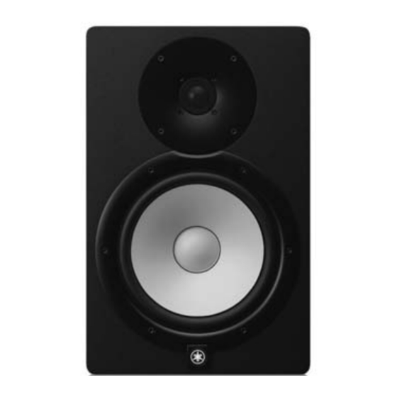
Yamaha Electone HS-5 Manuel d'entretien
HS8/HS7/HS5
5-2
HS8, HS7 :
Remove the fi ve (5) screws marked [300A]. The AMP
circuit board can then be removed together with the
heatsink 8B. (Fig. 5-1)
*
When installing the AMP circuit board with the
heatsink 8B, first tighten the two (2) priority screws
in order as shown in Fig. 5-1.
*
Be careful not to drop it.
HS5 :
Remove the three (3) screws marked [300B]. The AMP
circuit board can then be removed together with the
heatsink 5B. (Fig. 5-2)
5-3
Remove the two (2) screws marked [80] and the four
(4) screws marked [130]. The heatsink 8B (HS8, HS7)
/ 5B (HS5) can then be removed from the AMP circuit
board. (Fig. 6)
5-4
Unsolder the leads of the AMP circuit board. The
AMP circuit board and IC (POWER AMP) can then be
separated. (Fig. 6)
Rear view (背面から見た図)
Priority screw (2nd)
(優先ネジ (2) )
[300A]
[300A]
Priority screw (1st)
(優先ネジ (1) )
AMP assembly
(アンプAss'y)
10
<HS8, HS7>
Fig. 5-1 ( 図5-1)
[130] x 2
AMP
Soldering
(はんだ付け)
Bracket 8B
(ブラケッ ト8B)
[80]
IC (POWER AMP 68W)
5-2 
HS8, HS7:
 
[300A]のネジ 5 本を外し、ヒートシンク 8B と共
に AMP シートを取り外します。 (図 5-1)
  ※ 
ヒートシンク 8B 付き AMP シートを取り付けるときに
は、優先ネジ 2 本を図に示す順で先に締めてください。
(図 5-1)
  ※ 
落下させない様に注意してください。
 
HS5:
 
[300B]のネジ 3 本を外し、ヒートシンク 5B と共
に AMP シートを取り外します。 (図 5-2)
5-3 
[80] の ネ ジ 2 本 と[130] の ネ ジ 4 本 を 外 し、
AMP シートからヒートシンク 8B (HS8, HS7) / 5B 
(HS5) を外します。 (図 6)  
5-4 
AMP シートのハンダ付け部からハンダを取り除
き、 AMP シートと IC (POWER AMP) を別けます。
(図 6)
[300B]
AMP assembly
(アンプAss'y)
[130] x 2
Soldering
HS8, HS7 :
(はんだ付け)
Heatsink 8B
(ヒートシンク8B)
HS5 :
Heatsink 5B
(ヒートシンク5B)
[80]
Bracket 8A
(ブラケッ ト8A)
Fig. 6 ( 図6)
<HS5>
Fig. 5-2 ( 図5-2)