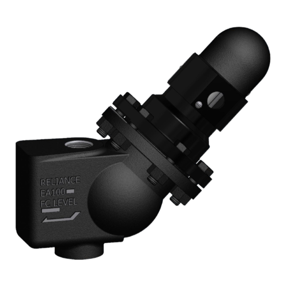
Clark-Reliance Levalarm EA100S Instructions pour l'installation et le fonctionnement - Page 5
Parcourez en ligne ou téléchargez le pdf Instructions pour l'installation et le fonctionnement pour {nom_de_la_catégorie} Clark-Reliance Levalarm EA100S. Clark-Reliance Levalarm EA100S 10 pages.

For Levalarms with optional probes, follow this procedure after piping has been connected to body of
the unit:
1. Install relay control unit at any convenient location, as the connecting wires may be of any
reasonable length up to 1000 ft. Verify that the control unit is rated for the correct supply line
voltage and frequency (cycles).
2. Install optional light indicator, or horn, or both at a convenient location for the operator.
3. Remove the probe fitting housing. This will give you access to the terminals on the probe
assemblies for wiring. Verify with a calibrated torque wrench that the probe fittings are torqued
to 40 Ft-Lb. The conduit bracket has an 7/8" Dia. opening for the conduit.
4. Wire per wiring diagram. See below.
5. Replace probe fitting housing.
The probe assemblies have a 5/8"-24 UNEF thread and are furnished with a copper or monel gasket.
Stainless steel rods are connected to the probes with a coupling nut to make a complete assembly.
Probe installation and maintenance instructions can be found in IOM #R500.E189-A-3. The probe(s)
can be removed for inspection and cleaning by merely removing them from the Levalarm body with a
7/8" deep well socket. When replacing the probes, be sure to lubricate the threads and use a new
gasket. Probes can usually be cleaned by wiping with a damp cloth. Future cleaning frequency will
depend upon conditions of boiler water. Routine blowdowns help keep probes clean. Refer to IOM
#R500.E156C.
RELAY CONTROL UNIT
Please refer to actual relay control unit drawing provided with your system for details. ECID Series
Relay specifications can be found in IOM #R500.E137E
MODELS WITH PROBES - EA100DP AND EA100SP
