Clarke 7120310 Manuel d'utilisation et d'entretien - Page 7
Parcourez en ligne ou téléchargez le pdf Manuel d'utilisation et d'entretien pour {nom_de_la_catégorie} Clarke 7120310. Clarke 7120310 17 pages. Cpe water pump
Également pour Clarke 7120310 : Manuel d'utilisation et d'entretien (16 pages)

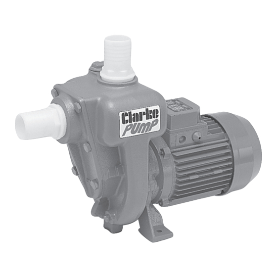
PIPE/HOSE CONNECTIONS
The pump inlet and discharge
ports are both 1
female threads and accept the
adaptors supplied.
Hoses with the same diameter
should be used and secured to
the adaptor with a suitable hose
clip.
Ensure all connections are air
tight when under pressure but not
so tight as to crack the plastic
inlet/outlet adaptors.
These notes are for guidance on
how to achieve a proper working system. The diagram (Fig. 1) above shows a
typical installation at the pump.
A foot valve and filter should be fitted to the lower end of
the suction hose, as illustrated in Fig. 2, so as to retain water
in the suction system and more importantly, to prevent the
possibility of large foreign objects entering the pump body.
FURTHER CONSIDERATIONS
• Strain caused by vibration can be reduced by
connecting a short flexible hose between any rigid
pipework and the pump.
• We recommend that you always use pipes/hoses
with a minimum diameter of 1
• Any restriction in the pipeline will greatly reduce the
flow.
• Ensure that the hoses and pipes are supported along their entire
length. They will be considerably heavier when filled with water.
• We recommend that you install isolation valves either side of the
pump in order to isolate the pump during maintenance/removal.
• A gate valve may be installed in-line on the delivery side of the
pump which can be adjusted as required to regulate the flow of
water and can assist in priming the pump.
Parts & Service: 020 8988 7400 / E-mail: [email protected] or [email protected]
½
" BSP (38 mm)
½
" (38 mm).
7
