Alemite 7785 Series Manuel d'entretien - Page 11
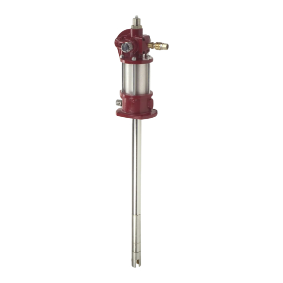
Parcourez en ligne ou téléchargez le pdf Manuel d'entretien pour {nom_de_la_catégorie} Alemite 7785 Series. Alemite 7785 Series 14 pages. High-pressure grease pump

High-Pressure Grease Pump
33. Install Roll Pin (41).
• Use a small hammer.
34. Install Valve Seat (49), Plate (50), and Stop Nut (51)
onto the Primer Rod.
• Tighten the Stop Nut securely. Place a small punch
into the hole of the Primer Rod to prevent its rotation
35. Position Adapter (43) horizontally into the vise.
Internally-Threaded End of Adapter
36. Install Gasket (29) into the internally-threaded end of
the Adapter.
37. Install the Primer Rod and Piston assembly
(Piston end first) into the Adapter.
• Center and seat all components properly. Pull on the
Piston as necessary. Use care to ensure the Gasket
does not move.
38. Install the additional Gasket (29) onto Valve Seat (49).
Externally-Threaded End of Adapter
39. Install Spacer (34) into the externally-threaded end of
the Adapter.
• Make sure the Spacer centers and seats properly.
40. Install Gasket (29) into the Adapter.
41. Position Barrel assembly (30) with the large diameter
pointing upward.
42. Install Wear Ring (31) into the Barrel Assembly.
43. Install and seat Seal (32) [lip end first] into the Barrel
Assembly.
44. Install Bearing (33) into the Barrel Assembly.
CAUTION
Use care installing the Barrel Assembly over the
threads of Piston (35). Damage to the Seal can
occur.
45. Install the Barrel Assembly (large diameter first) onto
Piston (35).
• Make sure the Barrel Assembly seats properly
against Spacer (34).
46. Install Gasket (29) onto the Barrel Assembly.
47. Screw the upper and lower Couplings (25) onto each
end of Pump Tube Rod (27) until the Spring Clip holes
align.
48. Install Spring Clips (26).
Alemite, LLC
1-800-548-1191-http://[email protected]
49. Screw the Rod and Coupling assembly onto the Piston.
• Install the Spring Clip.
IMPORTANT: If a primer is used with
Loctite 222, the curing time is greatly
reduced.
50. Screw Pump Tube (28) onto Adapter (43)
[with Loctite 222]. See Figure 2-B.
• Do not tighten.
51. Screw Primer Body (52) [with Loctite 222] into the
opposite end of the Adapter. See Figure 2-B.
• Do not tighten.
52. Screw Jam Nut (23) onto the Pump Tube.
53. Push on Plate (50) to expose Coupling (25) from the
Pump Tube as necessary.
Attach Pump Tube to Air Motor
54. Screw the Coupling onto the air motor piston rod until
the Spring Clip holes align.
• Rotate the entire pump tube assembly.
55. Install the Spring Clip.
56. Screw the pump tube assembly into Body (12).
57. Place a large wrench or other suitable tool into the slot
of Primer Body (52).
• Tighten all the components of the assembly securely.
Crush all gaskets.
58. Tighten Jam Nut (23).
Operation
Bench Test and Prime
NOTE: Perform the following procedures at
a pressure not to exceed 40 psi (2.8 Bars).
1. Make sure air pressure at the regulator reads zero.
2. Connect a product hose to the pump's material outlet.
3. Place the hose into an appropriate collection container.
4. Install Air Connector (2) to the inlet of the Air Motor.
5. Connect an air line to Air Coupler (3).
6. Connect the Air Coupler to the Connector.
7. Slowly supply air pressure to the pump's motor.
• The pump assembly should cycle.
If the pump assembly does not cycle, refer to the
Troubleshooting Chart for details.
11
SER 7785-A5
Revision (11-08)
