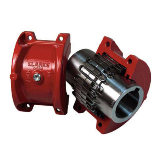
Clarke C10 Manuel d'application, d'installation et d'entretien du produit - Page 6
Parcourez en ligne ou téléchargez le pdf Manuel d'application, d'installation et d'entretien du produit pour {nom_de_la_catégorie} Clarke C10. Clarke C10 10 pages. Electric motor driven fire pumps

Table 2 – Misalignment & End Float
Installation Limits
Size
Parallel
Angular
Offset
(P)
Max
Max
Max
Inch
Mm
Inch
C1040T
.006
0,15
.003
C1050T
.008
0,20
.004
C1060T
.008
0,20
.005
C1070T
.008
0,20
.005
C1080T
.008
0,20
.006
Table 3 – Coupling Cover Fastener Identification
Size
C1040T – C1080 T
PARTS IDENTIFICATION
All coupling parts have identifying part numbers as
shown below. When ordering parts, always SPECIFY
SIZE and TYPE shown on the COVER.
PARTS INTERCHANGEABILITY
GRIDS – Size C1040T thru C1080T tapered grid
couplings use blue or non-painted grids.
CAUTION: Blue or non-painted grids may be used in all
applications, but DO NOT substitute orange grids for
blue or non-painted.
COVERS – CAUTION: DO NOT mix cover halves of
different designs.
HARDWARE – The new style covers use hex head
metric cap screws. Specify the style cover when ordering
replacement parts.
Hub Gap
Parallel
(x-y)
10%
Offset
Max
Max
Mm
Inch
mm
Inch
0,08
.125
3
.012
0,10
.125
3
.016
0,13
.125
3
.016
0,13
.125
3
.016
0,15
.125
3
.016
Metric Fastener
Property Class 10.9
Operating Limits
End Float
Angular
Physical
(x-y)
Limit (Min)
(P)
2 x F
Max
Max
Max
Mm
Inch
Mm
Inch
0,30
.013
0,33
.211
0,41
.016
0,41
.212
0,41
.018
0,46
.258
0,41
.020
0,51
.259
0,41
.024
0,61
.288
Page 6 of 10
Cover
Fastener
Maximum
Tightening
Allowable
Torque Values
Speed
Inch or Metric
(rpm)
Series
Fasteners
mm
in-lb
Nm
5,36
100
11,3
3600
5,38
200
22,6
3600
6,55
200
22,6
3600
6,58
200
22,6
1800
7,32
200
22,6
1800
Lube Wt.
lb
kg
.12
0,05
.15
0,07
.19
0,09
.25
0,11
.38
0,17
