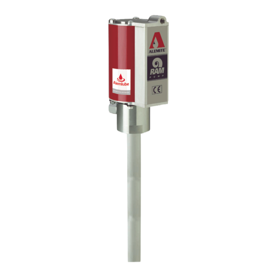
Alemite 9911-R1 Manuel d'entretien - Page 9
Parcourez en ligne ou téléchargez le pdf Manuel d'entretien pour {nom_de_la_catégorie} Alemite 9911-R1. Alemite 9911-R1 12 pages. High-pressure stripped pump
Également pour Alemite 9911-R1 : Manuel d'entretien (12 pages), Manuel d'entretien du propriétaire (16 pages)

SER 9911-1
1
Figure 4 Pump Tube Assembly - Section View
Revision (4-02)
Refer to Figure 2-A and 2-B Parts List
for Parts Identification
Step for all Models except 9911-1
8. Screw the Piston assembly onto the
Extension until the Pin holes align.
• Secure the Piston to the Extension
with Roll Pin (20).
Step for Model 9911-1 Only
Screw the Piston assembly onto the
Rod until the Pin holes align.
• Secure the Piston to the Rod with
Roll Pin (20).
9. Screw Primer Rod (34) into the Piston
assembly until the Pin holes align.
• Secure the Piston assembly to the
Primer Rod with Roll Pin (25).
10. Install and seat Bearing (26), Seal (27)
[heel end first], and additional Bearing
(26) into the externally threaded end
of Lower Tube (29).
11. Install and seat Gasket (28) into the
internally threaded end of Upper Tube
(18).
12. Screw the Lower Tube [with Loctite
222] into the Upper Tube.
• Follow the thread sealant
manufacturer's recommendations.
• Do not tighten at this time.
13. Install the Rod assembly into the
Upper Tube until it protrudes from the
Lower Tube.
• Use care not to damage the Seal.
14. Install Seal (31) [heel end first] into
Foot Valve (32).
15. Install Stop (30), the Foot Valve
assembly [Seal end first], Gasket (28),
Seat (33) [small diameter end first],
and additional Gasket (28) over the
Primer Rod and into the Lower Tube.
16. Install Primer Disk (35) onto the
Primer Rod.
• Make sure the hole align.
17. Install Roll Pin (36) that secures the
9
High-Pressure Stripped Pump
Model Dependent Step
IMPORTANT: If a primer is
used with Loctite 222, the
c u r i n g t i m e i s g r e a t l y
reduced.
Alemite Corporation
