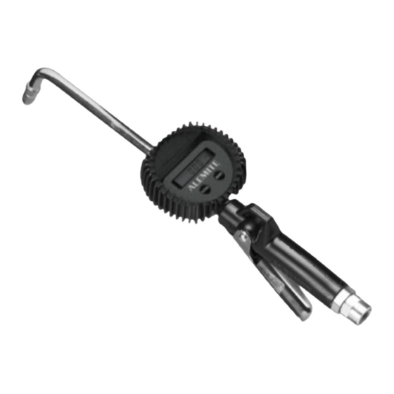
Alemite 3620 Manuel d'entretien - Page 5
Parcourez en ligne ou téléchargez le pdf Manuel d'entretien pour {nom_de_la_catégorie} Alemite 3620. Alemite 3620 11 pages. Electronic-metered control valve

Electronic-Metered Control Valve
Overhaul
NOTE: Refer to Figure 2 for component
identification on the major components of
the valve assembly.
Prior to performing any maintenance procedure, the
following safety precautions must be observed. Personal
injury may occur.
WARNING
Do not use halogenated hydrocarbon sol-
vents such as methylene chloride or 1,1,1 trichlo-
roethane in this valve assembly. An explosion can
result within an enclosed device capable of con-
taining pressure when aluminum and/or zinc-
plated parts come in contact with halogenated
hydrocarbon solvents.
Release all pressure within the system prior to
performing any overhaul procedure.
• Disconnect the air supply line from the pump
motor.
• Into an appropriate container, operate the
control valve to discharge remaining pressure
within the system.
Never point a control valve at any portion of your
body or another person. Accidental discharge of
pressure and/or material can result in personal
injury.
Read each step of the instructions carefully. Make
sure a proper understanding is achieved before
proceeding.
Disassembly
Metered Control Valve
NOTE: The following procedures pertain to
all models of metered control valves in the
3620 series.
1. Unscrew the extension assembly from Meter
Assembly (2).
2. Separate the components of the extension assembly.
3. Unscrew Control Valve Handle (4) from Nipple (3).
NOTE: Nipple may separate at the Meter
Assembly.
4. Unscrew the Nipple from its component.
Alemite LLC
1-800-548-1191-http://[email protected]
Non-Drip Nozzle (Automatic w/ Manual Lock)
NOTE: Refer to Figure 3 for component
identification.
1. Unscrew Nozzle (16) from Angle Body (21).
2. Remove O-Ring (17) from the Nozzle.
3. Remove Stem (19) from the Nozzle.
Item
Description
No.
16
Nozzle
17
O-Ring, 1/2 " ID x 5/8 " OD
18
V-Block
19
Stem
20
Spring
21
Body, Angle
22
Gasket
23
Washer
24
Screw Assembly
Legend:
Parts are not available separately
designates a repair kit item
Repair Kit
Part No.
Kit Symbol
393518
Figure 3 Nozzle Assembly 318400-2 - Exploded View
5
SER 3620
Notes
Qty
1
1
1
1
1
1
1
1
1
Description
Kit, Repair
Revision (11-05)
