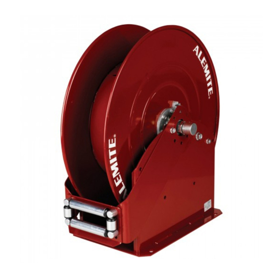
Alemite 7340 Manuel d'entretien - Page 8
Parcourez en ligne ou téléchargez le pdf Manuel d'entretien pour {nom_de_la_catégorie} Alemite 7340. Alemite 7340 16 pages. High-capacity
Également pour Alemite 7340 : Manuel d'entretien (12 pages)

Installation
WARNING
Do not exceed the lowest pressure rat-
ing of any component in the system.
Never point a control valve at any
portion of your body or another person.
Lubricant discharged at high velocity
can penetrate the skin and cause severe
injury. Should any fluid appear to punc-
ture the skin, get medical care
immediately.
Ensure all components are in opera-
ble condition. Replace any suspect parts
prior to operation. Personal injury can
occur.
Hold the delivery hose securely until
the reel is securely latched or fully
retracted. Uncontrolled retraction can
result in personal injury.
Reel Mount
NOTE
Should the reel mount to the ceiling or a
wall, it may be advantageous to lessen
its weight with the removal of the power
spring assembly.
Follow the appropriate procedural steps
within the section entitled
Overhaul, page 4.
Delivery hose type and length comparison to power spring tension in number of turns
Delivery hose description
3/8 in ID two-wire braid
1/2 in ID single-wire braid
1/2 in ID single-wire braid
1/2 in ID air
1/2 in ID air
1 Mount the reel assembly with the proper
hardware.
CAUTION
Never connect rigid piping to the Swivel
assembly. Damage to components can
occur.
2 Screw a connecting hose (with thread
sealant) into the swivel assembly.
3 Attach the connecting hose to the supply
line.
NOTE
Anchor the connecting hose to a suita-
ble surface to prevent the hose from
flexing at the swivel assembly.
The anchor should be in-line with the
inlet of the swivel to minimize side
loading (→ fig. 3, page 9).
Setting power spring tension
4 Make sure there is no tension on the
power spring assembly.
NOTE
Wear non-slip gloves when handling the
sheave assembly.
5 While facing the ratchet, turn the sheave
assembly clockwise to set the tension
suggested for the type and length of
delivery hose used (→ table 3 for
details).
6 Allow the reel to latch.
Length of hose
80 ft. (24,4 m)
80 ft. (24,4 m)
100 ft. (30,5 m)
80 ft. (24,4 m)
100 ft. (30,5 m)
8
Delivery hose attachment
WARNING
Precautions must be taken to ensure
the sheave assembly remains engaged
with the ratchet. To prevent movement
either:
• instruct an assistant to grip the
Sheave securely with non-slip gloved
hands or
• install a clamp on the sheave
(→ fig. 4, page 10).
Personal injury can occur.
Once the sheave assembly is secure:
7 Install the delivery hose through the
guide assembly.
8 Connect the delivery hose to the 90 °
union.
8.1 Make sure the connection is secure.
NOTE
Orient the hose to allow its natural
curve to match the sheave.
This reduces torque load on the
power spring assembly and eliminates
the tendency of the hose to stack on one
side of the sheave.
Number of turns
23
20
23
19
23
Table 3
