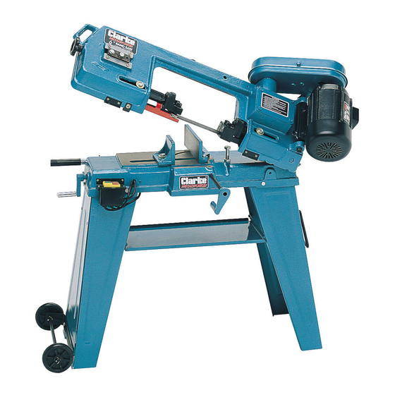
Clarke Metalworker CBS45MD Manuel d'utilisation et d'entretien - Page 8
Parcourez en ligne ou téléchargez le pdf Manuel d'utilisation et d'entretien pour {nom_de_la_catégorie} Clarke Metalworker CBS45MD. Clarke Metalworker CBS45MD 19 pages. 6” (152mm) bandsaw

Assembly
This machine cannot be handled without the use of lifting tools. Take all
necessary precautions when manoeuvring.
For ease of packing and transportation, the bandsaw comes partly
assembled. It is therefore necessary to complete the assembly as follows.
Unpack and lay out all the items and identify each one by referring to the
Parts List and Fig. 1.
Should there be any deficiency, you should immediately contact the
dealer from whom the equipment was purchased.
If there is any uncertainty regarding electrical connections, you should
PLEASE NOTE THAT ALL REFERENCES TO ITEM NUMBERS IN THIS MANUAL REFER TO THE PARTS
LIST ITEM NUMBER. ALL ALPHA ITEM REFERENCES REFER TO FIGURE 1.
1. Legs and Tray Assembly
The legs (items Q & R) are a three sided section, one side of which is hinged.
Lay the legs on their sides, with the open ends facing each other and
approx. 18" apart. Locate the tray (item G) and attach between the legs,
ensuring it is the right way round, (i.e. tray uppermost), using the four nuts
bolts and washers supplied. Leave the nuts finger tight at this stage.
Important: Ensure the special "D" shaped washer is inside the leg, next to the nut.
Stand the assembly upright which will form a rough "A" frame, and with
assistance, gently lower the main body on to the legs. Firmly secure the
main body to the legs, using the three nuts and bolts at the top of each leg,
ensuring there is no distortion and that the assembly is completely stable.
Note that the legs may fit either way round.
Finally tighten the tray nuts and bolts, again checking for distortion and
stability.
2. The Pulley Guard and associated components.
The pulley guard (item B) sits over two shafts, one from the motor, (item A),
the other from the gearbox (item O), which drives the blade. The gearbox
shaft extends through a circular plate (Parts list item no. 18) secured by
three screws. It is necessary to remove the uppermost of these screws
IMPORTANT!
CAUTION
consult a qualified electrician.
8
