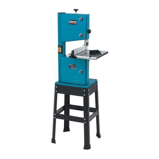
Clarke WOODWORKER CBS250 Manuel d'utilisation et d'entretien - Page 10
Parcourez en ligne ou téléchargez le pdf Manuel d'utilisation et d'entretien pour {nom_de_la_catégorie} Clarke WOODWORKER CBS250. Clarke WOODWORKER CBS250 13 pages. 45 mm (10”) bandsaw & stand
Également pour Clarke WOODWORKER CBS250 : Instructions d'utilisation et d'entretien (20 pages)

Fit the aluminium profile with scale, to the front of
the table using four bolts and washers supplied,
ensure the cut out in the aluminium carrier is lined
up with the T slot in the table. DO NOT overtighten
the bolts, the aluminium profile is required to be
removed when changing or fitting new sawblades.
Setting The Table Square With The Sawblade
Set the table square to the sawblade by loosening the knob,
adjust the table so that the pointer lines up with the 0 position
on the scale. (see Fig. 7).
The table can be tilted to an angle of 45° to the sawblade. To tilt
the table, loosen the knob, tilt the table top the required
angle. The angle can be set by lining up the angle
required on the scale with the pointer, it is
recommended to check the correct angle setting, by making
trial cuts in scrap pieces of wood.
Always ensure the table is secured in position, by tightening the
knob before attempting to use the saw.
Attach the rip fence by locating the guide pins into the
groove on the aluminium profile, see Fig. 8, lower the hook
over the back edge of the table and lock into position with
locking lever.
NOTE: when using the bandsaw with the table tilted, the rip
fence must be fitted to the right of the sawblade.
IMPORTANT
Before plugging in and switching the machine ON, open the upper and lower
band wheel doors.
Slowly rotate by hand, the upper band wheel in a clockwise direction only, observe the
sawblade, which should run in the centre of both wheels, if the blade tracks off, carry out
the tracking adjustment, if not your machine is ready for use.
ADJUSTMENTS
Tracking
Before carrying out this adjustment, all six blade guides must first be backed off, 3 above
and 3 below the table. Also remove the table insert.
Open the upper and lower doors
Release the handwheel lock, (see Fig. 9), by turning it
anticlockwise.
Whilst slowly rotating the upper blade wheel clockwise, slowly
turn the handwheel at the rear of the machine, (see Fig. 9),
observe the sawblade, if it tracks in the desired direction,
continue to turn the handwheel in the same direction until the
blade runs in the centre of the blade wheels, if the blade
A
Fig. 6
luminium Profile
Pointer
Knob
Scale
Fig. 7
Fig. 8
Fig. 7
Handwheel
Fig. 9
Lock
-8-
Mitre Cutting
Most crosscut work, especially with small pieces
is more easily controlled with the use of a mitre
guide The mitre guide is also essential for
accurate mitre and compound mitre cuts. The
guide is graduated to 60
O
for both left and right
hand angles.
WARNING
For your protection, ALWAYS use a push stick, this
can easily be replaced, your fingers cannot
MAINTENANCE
BEFORE CARRYING OUT ANY SERVICING OR MAINTENANCE, DISCONNECT
THE MACHINE FROM THE POWER SUPPLY
CHANGING TYRES
Eventually the rubber tyres on the bandsaw blade wheels will wear due to the constant
contact of the sharp teeth of the blade. Lift the edge of the tyre with a small screwdriver
and the tyre can be worked off the wheel easily. We recommend that both tyres are
changed at the same time.
B
LADE GUIDES
Blade guides should be inspected regularly for wear or chipping, and replaced if
necessary.
B
EARINGS
All bearings used in the construction of your bandsaw and its motor are sealed and
lubricated for life.
CLEANING
Accumulated dust and chips should be removed from inside the bandsaw frequently.
Open the doors, of the upper and lower blade wheel housings, use a soft brush and/or
vacuum cleaner to remove sawdust, DO NOT use compressed air. At the end of every
work session, clean sawdust away from the motor vents.
-13-
