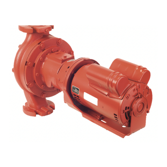
Armstrong S69 Instructions d'installation et d'utilisation - Page 5
Parcourez en ligne ou téléchargez le pdf Instructions d'installation et d'utilisation pour {nom_de_la_catégorie} Armstrong S69. Armstrong S69 10 pages. In-line ecm circul ating pumps
Également pour Armstrong S69 : Instructions d'installation et d'utilisation (4 pages)

Input demand
There are two methods of setting the input demand using the
PerfectSpeed® User Interface box.
Table 3 – Input demand options
Input demand
Definition
setting method
Set with On-Board
The input demand can be set via the On-
Potentiometer
Board Potentiometer. An external input is
not necessary.
0V to 10V
When an external controller is connected,
Set with
the On- Board Potentiometer should be
DC
control signal
set fully ccw (0%). Otherwise, the actual
demand seen by the pump is offset by the
setting of the On- Board Potentiometer.
Connection diagrams
There are two methods of setting the Input Demand. See Table
3 for definitions of the two options.
Table 4 – Setting input demands options
set with on-board potentiometer
set with 0 V to 10V DC control signal
In-line circulating
pumps
AC line connections
Check to see if the line voltage matches the nameplate voltage.
connections
green/verde screw
ground
Configuration scenarios
This section provides examples of different configurations and
briefly describes how the motor operates under those conditions.
Operating parameters
Speed will change linearly based on the On-Board Potentiometer
or remote 0V to 10V DC signal. The graph below illustrates the
operation of a motor adjusted with the On-Board Potentiometer.
At 0.5V DC signal, the motor will come on at 30 0 rpm and
ramp linearly to 18 0 0 rpm for ECM series circulators.
Adjusting pump speed (rpm) with on-board potentiometer
i n sta l l a t i o n &
o per at i n g i n str uct i o n s
5
