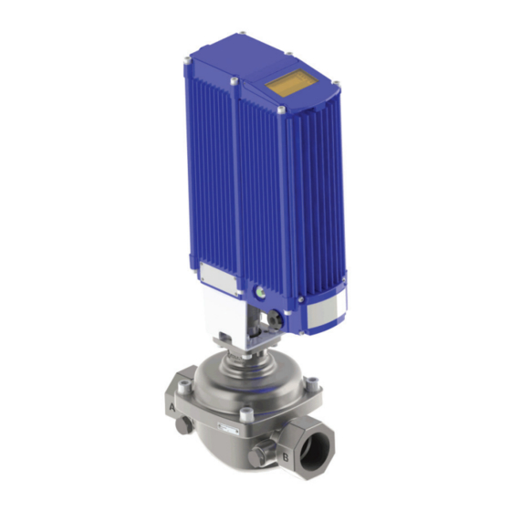
Armstrong Emech F2 Manuel d'installation, d'utilisation et d'entretien - Page 11
Parcourez en ligne ou téléchargez le pdf Manuel d'installation, d'utilisation et d'entretien pour {nom_de_la_catégorie} Armstrong Emech F2. Armstrong Emech F2 20 pages. Steam water mixing valve

CAUTION:
Prior to installation ensure that the pipes leading to the valve are clear from debris which may block or
damage the valve on commissioning.
WARNING:
Only trained personnel familiar with pipe work and pressure systems should install and maintain
Emech equipment. Failure to do so may result in serious personal injury!
WARNING:
Depressurize pipe work to atmospheric pressure and drain all fluids from the pipe work before working
on the valve. Failure to do so may result in serious personal injury!
WARNING:
Ensure that the intended maximum operating pressure of the line does not exceed the pressure rating
of the valve. Failure to do so may result in serious personal injury!
WARNING:
The valve must be supported adequately so as not over stress the pipe work and or the valve body.
See Figure 5 and Table 2.1 below for the maximum nozzle loads on the valves. Application of loads above
these values may result in serious personal injury and or equipment damage!
Nozzle Load Orientations
Armstrong International
221 Armstrong Blvd., Three Rivers, Michigan, 49093 - USA
Phone (269) 279-3602 Toll Free (888) HOT-HOSE (468-4673)
2.0 Flow Control Valve - Model F2
When installing the valve in line, be sure
to follow good practice using either
sealing tape or thread adhesive in the
joints.
The valve may be attached straight to the
pipework.
NOTE: Be sure to consider the ease of
removing the valve should this become
necessary in the future. See images 3 and
4 below for typical installation methods.
NOTE: For valve maintenance, the bonnet
screws can be removed and full access to the
internal components is possible.
The valve may be connected to the pipe
work with a union style of fitting.
The valve may be connected to the pipe
work with a thread adapter and a clamp
style fitting. e.g. Tri-Clover™.
TABLE 2.1: Maximum Nozzle Forces and Moments for Flanged and Screw end F2 valves
020 F2
56 lbf. (250 N)
45 lbf. (200 N)
025 F2
90 lbf. (400 N)
72 lbf. (320 N)
040 F2
180 lbf. (800 N)
144 lbf. (640 N)
050 F2
450 lbf. (2000 N)
360 lbf. (1600 N)
Installation
620 lbf.in (70 Nm)
496 lbf.in (55 Nm)
1150 lbf.in (130 Nm)
920 lbf.in (105 Nm)
1150 lbf.in (130 Nm)
2124 lbf.in (240 Nm)
1150 lbf.in (130 Nm)
4248 lbf.in (480 Nm)
Designs, materials, weights and performance ratings are
approximate and subject to change without notice. Visit
armstronginternational.com/emech for up-to-date information.
11
